Recognizing that the overwhelming proportion of all flying
accidents are caused by errors of the pilot judgment, the General Aircraft "Skyfarer"
was designed to anticipate and make inherently impossible these human mistakes.
According to the designer, Otto C. Koppen, professor of Aeronautical Engineering
at M.I.T., the Skyfarer cannot slip, skid or spin nor does it lose control when
stalled. It is placarded as "characteristically incapable of spinning" by the
C.A.A.
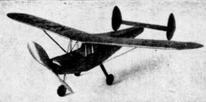
The Skyfarer is a high-wing monoplane, seating
two passengers side-by-side; it is powered by a four cylinder Lycoming engine of
75 horsepower. Most unusual is the fact there is no rudder -- turns being made
by the ailerons. The ailerons are operated by a steering wheel which also steers
the front wheel of the tricycle landing gear in much the same manner as an
automobile. The ship is equipped with flaps which contribute to the control of
takeoffs and landings.
In performance the Skyfarer compares favorably
with other lightplanes. With a geared Lycoming engine top speed is 100 miles per
hour. It climbs at a rate of 550 feet per minute and cruises for 400 miles at
about 20 miles to a gallon of fuel. Because of the tricycle landing gear and
hydraulic brakes, landings can be made at speeds from 45 to 80 miles per hour.
Other specifications are; Wing span 31 feet, 5 inches; length 22 feet. The
useful load is 460 pounds, gross weight is 1350 pounds.
Because of its excellent proportions and
interesting construction, this plane is ideally suited for a flying scale
replica. The model was developed from data supplied by the manufacturer and is
exactly to scale except for enlarged propeller and added dihedral. In spite of
its snappy appearance, it flies very well. Standard construction methods are
used throughout, so little difficulty should be experienced as your Skyfarer
takes form.
Fuselage
A simple rectangular frame is the backbone of the
fuselage structure; it is shown lightly shaded. Work directly over tracings of
the plan and build two side frames, one atop the other to make certain they will
be identical. While it is not absolutely necessary, it is best to steam or soak
the longerons in hot water so they will dry with a natural curve, as required;
this will aid in keeping the structure from springing out of shape. Hard grade
wood is used and longerons and uprights are 3/32" sq. stock. Invert the
completed sides over the top view and cement 3/32" sq. pieces to place at the
body center; when dry, draw the backs inward and place the remaining
cross-pieces. It will be necessary to crack the longerons so that they can be
pulled into position at the front.
Cut the formers shown on page three of the plans
from 1/16" sheet. Now, if the basic structure is dry, remove it from the
workboard and attach the formers to their correct positions. The wing center
section is constructed directly atop the fuselage; make this very accurately as
the wing's correct placement is determined by its position. Since the stringers
are merely fairing strips, they should be medium-soft balsa; they are cemented
directly to the underframe except where there are formers, of course.
Before the nose can be completed it is necessary
to attach the front landing gear fork. A full scale plan of the fork is given.
Bend the halves from .034 music wire and then join them by soldering. Align the
fork properly against former LG-1; then using needle and thread, firmly sew it
to place. Apply several coats of cement over all the former and adjacent
structure.
The rear landing gear strut can be made at this
time also; it is bent from .040 music wire. The method of attachment is
indicated by the perspective. A 5/16" deep piece of hard 1/16" sheet is cemented
to the vertical members at section 5S. The wire strut is then fitted over this
member and securely lashed to place by wrapping with thread. Add the triangular
1/16" sheet gussets, shown, and apply several coats of cement. Rubber tubing and
balsa fairings are not added until later.
The nose is covered with light grade 1/32" sheet;
all the shaded area, as indicated on the plan, is covered. Three or four
individual pieces will be required. Cement the sheet to the adjacent frame,
using pins and rubber bands to hold it in place until dry. The extreme front of
the nose is made removable to permit the rubber motor to be stretched for
winding. Roughly cut the nose block to shape, lightly cement to the fuselage and
sand the entire front smooth and uniform. Remove the nose block and cement a
piece of 3/16" sheet to the back so it will fit to the opening in section No. 1.
The rather blunt tail piece is carved from a very soft balsa block; it is
hollowed, as shown.
Tail Surfaces
Construction of the tail surfaces is simple.
First build flat frames for the two rudders - or rather fins - and stabilizer
using 1/16" thick stock for the outlines and 1/16" sq. strips for the ribs. To
give the stabilizer a streamline cross section, cement soft strips of 1/16" sq.
to each side of each rib and then, when dry, cut them streamline. The fins are
of flat construction. Trim and sand each structure to complete the tail surfaces
construction.
Wing
Only the right wing plan is shown so it will be
necessary to prepare an accurate plan of the left wing in order that
construction can be done directly atop it. With exception of the two 1/16" thick
end ribs, all wing ribs are cut from 1/32" sheet. Taper and sand the tailing
edges before pinning them into position over the plan. Pin the ribs to their
respective positions, then attach the leading edges and spars. Assemble the tip
pieces which are cut from 3/32" sheet and cement the tips to place. Once the
leading edges and tips are cut and sanded to shape the wing frames are
completed.
Propeller
The propeller blank is shown in perspective on
the plan. Select a hard block of the proper size and shape the blank as
indicated. Drill the tiny hole for the prop shaft before starting to carve a
right-hand prop. The hardness of the balsa will determine the blades' thickness,
the shape of which can be seen in the photos. Thoroughly sand the propeller and
apply several coats of clear dope with light sanding between each coat to
produce a nice smooth finish. Equip the prop with some kind of free-wheel device
so the glide will be improved. Cement a washer to the back of the propeller,
too.
Bend the propeller shat from .040 music wire.
Place several washers between the prop and nose block and then bend a loop on
the shaft front into which a mechanical winder can be hooked.
Covering
Being a scale model, it is necessary for the
covering to be nearly perfect. With this in mind carefully sandpaper all the
structure to remove every bit of roughness. Colored tissue is used and since
this is a commercial plane, most any color combination will be correct; our
original model was very attractive with its red and black color scheme. Cement
cellophane side windows to place before starting to cover the fuselage. The use
of numerous small pieces on curved parts will help avoid wrinkles; use only
enough banana oil adhesive to stick the extremities of the area being covered.
Individual pieces of tissue should be lapped neatly. The balsa cowling and
similar wood parts are tissue covered, too. Use a separate piece of tissue for
each side of each wing half, stabilizer, rudder, etc.; wing tips require
individual pieces, also. Once covered, all parts are lightly sprayed with water
to tighten the covering; to keep the wings and tail surfaces from warping they
should be pinned to a flat surface until dry. Clear dope is not applied until
later.
Assembly
The various parts are now assembled. A half
windshield pattern is given; cut a complete paper pattern and make certain it
will fit your model exactly before cutting one from celluloid. Avoid cement
smears when attaching the windshield.
The landing gear is completed next. Rubber tubing
of the correct diameter is slit and slipped over the upper portion of the front
fork. Cement the seam and then neatly wrap light twine or heavy thread about the
strut to represent the coil spring on the real ship. Tubing of smaller diameter
is slipped over the fork portion of the strut. The structure at the strut rear
is represented by thin balsa or bamboo strips. Cut the rear strut covers from
3/16" sheet; these members are of streamline cross section. Cut 1/16" deep
grooves in the struts to hide the wires, cement the wires fast; do not, however,
attach the tops of the struts to the fuselage. Cover the struts with several
layers of colored tissue.
Wheels are made from three laminations of 1/8"
sheet or they may be purchased. Cement washers to the wheels so they will
revolve accurately and smoothly. Before the wheels are attached to place they
should be color doped. The front fork will spring apart far enough to admit the
front wheel; rear wheels are held in place by washers soldered to the axles.
Assemble the tail surfaces by cementing the
rudders to the stabilizer; cut enough tissue from the rudders so a solid gluing
surface will be had. Remove enough tissue from the stabilizer undersurface so
the tail surfaces can be fitted accurately to the fuselage at the position
indicated. Attach the wings -- this will be an easy matter since the exact
position and angle has already been determined. Tips are elevated to the extent
of 1-1/4". Now that the model is assembled, a coat of clear dope can be applied
to all the covered surfaces.
Add the various more minor details to "dress-up"
your model Skyfarer and construction is finished. License numbers, fuselage
strips and similar decorations are cut from contrasting tissue; ailerons, flaps,
elevator, doors etc., are effectively represented by thin strips of black
tissue. The single wing struts are cut from 3/32" sheet; they are of streamline
cross section and join the wing at "X". Struts, propeller and other exposed wood
parts are color doped. Air intake openings in the cowl, exhausts and similar
details found on photos of the real ship can be added without harming the
model's flight ability.
Either 8 strands of 1/8" rubber or 6 strands of
3/16" rubber should be used to power the Skyfarer. Measure the strands to
correct length and then attach them to the loop on the prop shaft; drop the
rubber through the fuselage and slip the bamboo pin through the fuselage so as
to attach them in the rear.
Flying
To prevent damage to the model at this crucial
stage, test flights should be made in a field of tall grass, but if none is
available make first flights R.O.G. with a few turns. The descent from a hand
glide should be flat and smooth before power is applied, so a small corrective
weight may be required to obtain the desired results. Once the glide is good,
all further adjustments are made by offsetting the thrust line. A small sliver
of wood between the nose block and fuselage, tilting the thrust line down at a
slight angle, will help eliminate a tendency to stall, while right or left
thrust will make the ship turn as desired. Use a mechanical winder for long
flights -- stretch the rubber strands about 2-1/2 times normal length and store
up power. Now that your Skyfarer is completed we are sure you will be more than
pleased with its performance. Our original ship proved to be a consistent and
capable flyer; it is exceedingly fast in climbing and gains considerable
altitude for a ship of its size. The glide is flat and covers surprising
distances from high altitudes to come in for easy, realistic landings on the
tricycle gear. Happy landing!