THE first part of this article, "How to Build a Gas Powered Camera Model," was published in the May issue. Readers who may wish to build the model should read over the first part carefully before considering the instructions which follow. This plane is a very unusual ship in many respects.
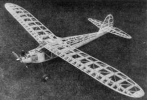
First of all, it is constructed to carry a small camera which, by means of a timer, takes a picture from the plane when it is in flight. On the whole the plane is a very fine performer. It climbs steeply but steadily when fully loaded, camera and all: and it has a glide that compares with the "best of them." It is not of makeshift construction but rather is a carefully engineered job that is worthy of the finest craftsman.
This model will serve well as a contest ship, and as such, has a fine rate of climb and excellent soaring qualities. It has about seven feet of area and with the camera weighs five pounds. Without the camera it weighs slightly over 4-1/2 pounds. This ratio of weight to area produces a wing loading of slightly over ten ounces per square foot.
|
|
|
|
|
|
The author is confident that those who undertake and finish the construction of this ship will be well repaid for all the effort put into it. The second part of the instructions follows:
Wing Panels
First cut out all the parts required, ready to assemble. Cut 12 full ribs front 1/16" sheet stock and 2 from 3/16" sheet balsa. Cut the remaining ribs for the tip area at the same time. Don't forget the necessary holes for the hardwood dowel pins. (Put dowel in after wing panel is constructed.) The leading edge is 5/16" sq., while the trailing edge is 1/8" x 1/2", tapered. The spars should be very hard balsa, of the same grade used in the center section. The front one is 1/8" x 1", while the rear one is 1/8" x 9/16". The two strips on the leading edge, which prevent the sagging of the doped covering at this point, are 1/16" x 1/8" balsa strips. The wing tips are 1/16" sheet material. To construct a wing panel, slide the ribs on the spars in their approximate positions. Then pin the spars in place and cement the ribs in their correct locations. Follow with the leading and trailing edge, etc. All diagonal wing bracing is 1/8" sq. stock.
When a panel is entirely completed, slide both of the dowel pins in their respective lengths of center section tubing and through the wing panel ribs at the same time. Make certain that the wing panel lines up with the center section perfectly in every respect. The wing stubs of the center section should be in perfect alignment, obviously. The importance of this operation cannot be emphasized too much. When satisfied, including sighting down the edges of both the panel and wing stub, cement the dowel pins in place, using metallic cement. When dry, each set of panel pins will be permanently in a correct, fixed position. Next, near the ends of the wing panel dowel pins as they rest in the tubing in position, drill a hole in each, right through the tubing and dowel together (about 1/16" diameter). These are for the safety wires which are dropped through when the ship is being assembled for flying. It will be necessary also to put balsa strips between the wing ribs (flush with rib surfaces) and install short lengths of 1/8" O.D. aluminum tubing between them and the larger tubing housing the wing panel pins. Do this on top and bottom. When wing is covered, a hole then remains straight through the wing section so that safety pins of aluminum wire can be dropped through and bent over.
Tail Surfaces
The construction of this unit is more or less conventional. Both the fin and stabilizer have been designed for maximum efficiency. The rather high position of the stabilizer on the fin adds greatly to the stability. This ship is absolutely guaranteed by its designer not to spiral dive under lower under any circumstances.
First cut all materials for the fin and stabilizer. All ribs are cut from 1/16" sheet balsa, with the exception of several where additional strength is required. To construct either one, first lay down the spar, raising it 3/16" at each end, because of the equal taper to each side of it. Pin in place the leading and trailing edge, and also raise them to correct positions from the workbench. The fin and stabilizer tips are 1/16" sheet material. Diagonal bracing is 1/8" sq. balsa. When both are completed, remove a section of rib No. 7 in the fin (just ahead of spar) so the stabilizer may be slipped in position. Be very sure that it is at right angles with the fin. Then cement it in place securely. Now, slide the hardwood dowel pins through the fin ribs and also place them in the aluminum tubing in the fin base which was installed earlier. Be certain that the stabilizer meets the surface of fin rib No. 8, equally, and also that it lines up with the wing (slide wing panels in center section to check this). To complete this operation, cement the pins securely and do not withdraw the empennage unit until dry. Between fin stub ribs Nos. 8 and 9, at the forward dowel pin, prepare another safety-pin hole, as was done for the wing panels in the center section of the wing. Mix some more paste of corn starch, clear lacquer, and aluminum powder and apply it in the corners between the fin and stabilizer, as you did in streamlining the fin stub and fuselage.
Covering and Finishing
Bamboo paper is used for covering, although silk is permissible, of course. In using bamboo paper, the job is much simplified. Incidentally, don't forget to attach a length of fine, strong thread on the flight timer arm extension for the camera shutter, dropping it through the hole provided in the cabin roof and through the pulley, before covering. Use only as large a section of paper at a time as is practical, to insure a smooth job.
In covering the fuselage sides and top from the cabin back, use clear dope for sticking on the corners only (top and bottom) of the fuselage. Stretch the panel of covering tightly over the side stringers, so that only they are seen when surface is doped and shrunk. Cover the nose of the ship with small sections also. Proceed with the landing gear, wing, and tail surfaces. When completed, first water‑shrink the covering, following with two coats of clear, full strength nitrate dope.
The writer's model was originally painted in bright red throughout, but after 5 months of continuous flying the color scheme was changed to all-white, with purple trim, and finished with a gold pin stripe between the two. Such a combination is very attractive and something "different." However, the color remains a matter of personal preference. In painting, all parts such as the cabin windows, timer arm, wheel axles, tail skid, and dowel pins must be masked off, using scotch tape (cellophane). Spray the paint job to obtain the finest finish. At least two coats of pigmented dope should be applied. Install the engine and secure the 3-1/2" air wheels on the axles by soldering washers on the ends.
To adjust the camera for operation, first secure it in its position on the mounting. Put a rubber band in the length of thread (coming down from the timer) between the pulley on the bulkhead and the shutter extension. On the end of the thread install a hook made from a pin. It is possible to make pictures any length of time after the take-off up to 50 seconds (about capacity of Autoknips timer) by merely inserting a series of "S" hooks in the line between the hook which was just put on and the shutter extension. In other words, the procedure of operation is to first wind up the flight timer, relieving the tension on the thread. The camera shutter is then snapped backward (holding the finger over aperture when loaded with film). As the timer brake is released and timer spring begins to wind down, the arm in the timer case which travels inward begins to pull on the shutter thread, over the pulley. Say for example it is done, and the camera shutter is found to snap forward in 20 seconds, and a longer period is desired. Merely add an "S" hook or two in the line at the shutter to raise the time. This decreases the tension of the shutter control thread slightly. Obviously, the camera is only able to take one exposure on each flight, but the film can be quickly rolled to the next exposure between hops.
Flying
First, check it for balance. If it balances with the nose slightly down, holding the wing on the fingers a third of the way back from the leading edge, with all surfaces in neutral position, it should be set for a flat glide. Hand gliding is not recommended but can be done if launcher is running fast enough to give it flying speed. Do not adjust the fin tab until the reaction on the glide has been observed. Torque does not bother the plane to any great extent due to the long moment arm. It should be adjusted for powered flight to the left and gliding to the right, in rather large circles. For test flights, set the flight timer for only about 25 seconds, and let it go with the engine about half throttle. The performance can be increased gradually by giving the motor more "supe" as the flight characteristics of the gas job are made evident.
The writer would be particularly interested in knowing of the results of flights with the model and also any good aerial photographs which are obtained by others. Anyone wishing further help on any specific part or parts of the construction may contact its builder, in care of MODEL AIRPLANE NEWS, and assistance will be gladly given.