|
|
|
The Plan Page
[ Home ] [ Previous Plan Pages ]
[ Special Things ] [ Earl Stahl Plans ]
gt-hunter1@home.com
|
|
|
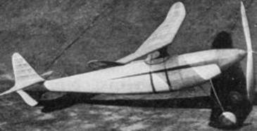
Building the "Tsetse Fly"
Super Wakefield Model
How This Stable, Efficient Plane Was
Developed and How You Can Build It
By FELIX GUTMANN
THOSE builders who have been waiting for THE supermodel, may terminate that waiting right here. This Grant designed Wakefield model is undoubtedly one of the finest flying models ever produced. It represents the ultimatum in refinement of stability and efficiency characteristics. Above all, its gliding qualities are unsurpassed. It is built to exact Wakefield specifications, having a wing of 200 square inches and a stabilizer slightly less than 33% of the wing area maximum. The weight is exactly 8 ounces, with 24 strands of 1/8" flat rubber. Tests have shown the model to have a gliding ratio of 15 to 1, remarkable for any model. This plane represents the results of scientific effort to produce a super model, and those efforts have been well rewarded.
The construction is not quite as simple as that of the average model, but the extreme pleasure involved in the production of a "flying tear-drop" more than makes up for the extra time required.
Due to the inappropriate weather during the winter months, when the model was built, it has never received a full wind-up.
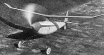
A high lift, high aspect ratio and efficient wing give remarkable climb and soaring qualities.
The model in full flight climbs stably, steadily and at a steep angle.
Superior construction is revealed in the framework.The times when it was tested, the weather was very cold and windy. The model was hand-wound only, and given but 200 winds with 24 strands. Upon being launched it rose up steeply and gracefully without swerving, to over 100 feet. It "turned in" 40 seconds to one minute flights consistently during these trials. An unbounded pleasure is to watch this model glide in. If the propeller was absent one might think it was a tow-launched glider coming in. The landings are always perfect. The large wheels allow landings on grass lawns without nosing over. They also greatly aid the stability of the model in flight. Take-offs are nothing but hops into the ether. In the very near future the model will be given an opportunity to show what it can really do with a full wind-up of about 800 turns. The results of this test will probably be published in the "Air Ways" column of this magazine.
Construction
Now for the actual construction of the model: All the ribs and bulkheads have already been carefully plotted and drawn up full size in the accompanying plans, so the builder is spared a great many hours of toil right here.
Wing
The rib outlines and stock sizes are on plate 5. The best way to transfer the rib outlines to the balsa is to use carbon paper. However do this only if the builder has drawing curves to carefully reproduce the airfoil. Another way is to use a hat pin with a beaded end. This is used as a pricker. Make a pin hole about every half inch over the straighter portions, and bring the holes closer together where the rib curves are more abrupt. This of course is done with the rib outlines over the balsa sheet. The beaded end will protect the finger. After all the ribs are transferred the holes on the wood are connected with a pencil line, thus completing the outline of each rib. Drawing curves also would insure a more accurate job here. Be careful not to accidentally superimpose or overlap two ribs on the balsa.
The ribs with notches for spars are then cut out with a sharp razor. The top view of the wing should be reproduced to full scale on a large piece of drawing paper or a board. It should be drawn twice, each one to represent a wing half. The wing should then be built right over the drawing. All sizes and grades of stock are listed on the wing drawing on plate 2. Care should be taken in the shaping of the leading and trailing edges. It is suggested that some of the new ready cut "V" trailing edge stock be used as this will save considerable time. Note that each wing half is to be built in one straight piece. After the wing halves are dry, they should be removed from the board, and the tip dihedral put in each wing, as shown in the front view of the wing. Set this aside to dry. When dry cement the two wing halves together at the center, applying the right amount of total dihedral.
After this is dry, cut out the wing center spars, as shown on the left bottom of plate 2, and cement them in place. When the cement of the wing structure has hardened, cut out the cap-strips. The best way is to take a whole sheet of 1/32" x 2" medium sheet balsa, cutting it down to the approximate length of the wing half, excluding the tip. Pin the balsa in place in the notch at the root rib provided for that purpose, and pin it in place on R-10. Now with a pencil make a small mark where the edge of the sheet touches each rib.
This done, remove the balsa and cut down each rib between R-1 and R-10 to accommodate the cap-strip. That is, cut each of these ribs just like the end ribs, around the nose. This is best done by using a razor. Make sure that the little strips cut out of the nose end of each rib is no thicker than 1/32". When this is done the ends of the cap-strip should be cut so as to fit R-I and R-10 perfectly. Note here that only half of a wing is worked on at a time, and only one surface, either top or bottom. The balsa is now glued in place, being fitted carefully into the notch in each rib. Use as many pins as necessary to hold it in place while drying. During this time work on the other half of the wing. When the second half is drying, the first half is probably dry, so remove the pins, and trim off all the extra balsa along the leading edge. Now the tip cap-strip may be glued in place. While this is drying remove the pins from and trim down the other half of the wing. The tip cap-strip is now glued on. The two tips, on top and bottom, are trimmed down as soon as dry. When all the cap-stripping is finished, it is sanded down perfectly smooth all around. The center piece may be glued in place on top. The wing will now be a thing of beauty and precision if all the workmanship has been scrupulously executed.
Tail
The tail is constructed just like the wing, except that the elevator is made in one piece. Only the rudder top is shown on the plan. The sub-rudder is made later. Since the plans are self-explanatory, no further description is necessary. Don't forget to put only a cap-strip on top of the elevator. Gluing the rudder on top of the elevator should be done very carefully. Make frequent reference to the perspective view on plate 2 if in doubt. Try to keep the tail construction as light as possible.
Fuselage
The first step in making the fuselage is to glue the blanks for the bulkheads. Plate 3 shows just how this is done. Make the front bulkhead blanks of heavy balsa. The length and width of the blanks may be obtained from the dimensions of the top and side views of the body. When all the blanks are dry, the bulkhead outlines are carefully transferred to the corresponding blanks, in the same manner as the ribs. The two balsa keels are cut out of 1/8" hard sheet balsa. They must be accurately scaled up making use of the secondary dimensions from the centerline. Mark off the positions of the bulkheads on each one. To start the monocoque construction, place two pins about 12" back from the nose end of the bottom keel, one on each side. That is, the keel is placed upright on the workbench, and at that point the two pins are stuck into the table so as to hold it upright. Place a block under the front end till it is 3" above the surface of the table. Now the tail end should be 4-3/4" above the table. Glue the front bulkhead in place on the keel and true it up with a triangle.
Now glue bulkhead B in place, true this up; now bulkhead C, and so on. Soon all the bulkheads will be in place on the bottom keel. Do this very carefully. Now the top keel should be glued in place. Note that the tail hook should be cemented in place on bulkhead M before it is set on the keel. Now the rest of the 1/8" square medium stringers are glued in place. The tail block is cut and glued in place, also the sub-rudder. This is cut from medium balsa and is reinforced around the edge by a bamboo or reed strip (see perspectives). It is a good idea to add a hard spar in the middle.
The nose plug is cut from heavy balsa. The landing gear is made according to plate 3. Note in detail X how two pieces of hard 1/8" x 1/4" strip are placed together, and a hole drilled through the middle to hold the main strut. Then the pieces are taken apart, and the strut is placed between them. After this they are glued together, bound well with thread and glued in place in bulkhead D as shown. It might be wise to reinforce this joint with a few diagonal strips of 1/8" square hard between C, D, and E around the joint. The rear strut detail is shown in Y. This should be glued well and bound with thread. The wheels should be of very heavy balsa, even a 3/64" hardwood ply center would be all right.
The body is covered with 1/32" plus sheet balsa, run along the body in strips, as shown in the plate 1 assembly view. This must be done with a great deal of precision. When the whole body is dry apply three or four coatings of banana oil with intermediate sandings with fine sandpaper.
Miscellaneous
The wing mount, propeller, tail door and bearing details are all shown on the plans, thus no extra words are necessary here. The propeller should be covered with silk which is applied with cement. When this is dry apply three coats of banana oil.
For power use 26 to 30 strands of 1/8" flat brown rubber. Lubricate this well and allow plenty of slack.
All wood parts of the model should have a high gloss finish..
The original model had red wings and tail and blue decorations on the wood parts. Apply all tissue with banana oil.
To make the wing saddle, glue two pieces of 1/32" medium hard balsa, 3" x 4-1/2", one on top of the other, and hold in place on top of the body at the position where the wing attaches. Use rubber bands. This will dry with the right curvature. The elliptical shape is now cut out and glued well to the bottom of the wing mount. See plate 3 for rest of details.
When the tail is glued to the top of the tail block it should have an incidence of plus one-half degree. The wing is held down with 1/8" flat rubber loops. Measuring from the thrust line, the incidence of the wing should be three degrees and the stabilizer one degree positive. The wing should be set at the same point as on the drawing (plate 3). In the construction of this model the tail end should be made as light as possible, and the front end of heavy balsa, to bring the center of gravity to the same point as on the drawing.
The writer would be glad to hear from anyone who builds this model and what results are obtained. Inquiries are welcome, but they should be accompanied by a self addressed, stamped envelope. Address the writer, c/o MODEL AIRPLANE News.
Scanned From June, 1938
Model Airplane News
![]()
![]()
![]()
![]()
![]()
[ Home ] [ Previous Plan Pages ] [ Special
Things ] [ Earl Stahl Plans ]