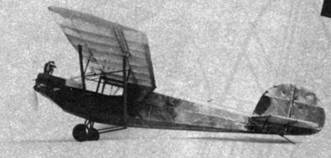
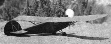
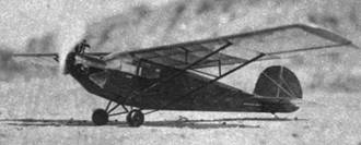
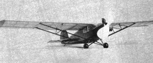
HERE is a well designed pre-war American lightplane that lends itself admirably to model building. It was in the same category as the 40 hp Piper Cub, being of the same general dimensions and performance. The Flyabout had ample room for two people and a puppy ---- so stated Aircraft Mechanics, the manufacturer. Two powerplants were available: the Continental A40 of 38 hp, and the Szekely of 45 hp, as reproduced on this model. A few specifications covering the Szekely powered type are:
|
Wingspan |
37 ft. 9 in. |
|
Wing loading |
5.51 lbs. per sq. ft. |
|
Net Weight |
590 lbs. |
|
Climb rate |
700 ft. per min. |
|
Overall length |
21 ft. 7 in. |
|
Power loading |
21.8 lbs. per sq, ft. |
|
Service Ceiling |
13,000 ft. |
|
Cruising Speed |
75 mph |
|
High Speed |
93 mph |
The scale of the model is 1/20 full size. All balsa used should be of firm texture unless otherwise specified.
|
|
|
|
|
|
FUSELAGE -- Begin by making the two side frames (shaded on drawing). Use 1/16" sq. and 1/16" x 3/32" for these. 1/16" x 1/8" stock is required for front portion of the lower longerons. Assemble the two frames in the usual way, first installing the crossbraces under the wing position. Notice that a few of the upper crossbraces, of 1/8" sq. balsa (between nose and rear of cabin), are set low to allow passage of the rubber motor. When the fuselage frame is completed to this point, cut out the required formers from 1/32" sheet balsa. Cement each in their respective positions. The 1/32" x 1/16" stringers should now be put in the nose as well as the single stringer which runs along the center on the bottom.
Cover these areas with 1/64" sheet balsa, using three separate pieces in covering the bottom as shown. After cutting the rear rubber hook bulkhead to shape, bend the rear rubber motor hook from No. 15 piano wire and insert in the bulkhead, following with the placing of the unit in the fuselage frame at rear as shown.
The nose block, of medium-hard balsa, is made next. It is simply cut to shape, plan and side views, and the resulting corners rounded off. Before cementing it against the fuselage frame, drill a hole for the propeller shaft to accommodate No. 15 piano wire. The front bearing is a dural aircraft type rivet, drilled for the same wire (running fit), and sunk in the nose block with cement in a counter-drilled hole.
The dummy Szekely engine can now be made and cemented in place. Each of the three cylinder units are identical, being built up with small bits of balsa. Wrap each with wire or thread to represent the cooling fins. The exhaust stacks and tappet gear are merely lengths of balsa dowel assembled with cement. The two valve springs on cylinder head can be made by wrapping fine wire on a nail. The twin-ignition sparkplugs on the forward side of each cylinder head are small pieces of balsa. The cylinder units are cemented on the nose block as shown on drawings at 120 degrees apart. Carve the instrument panel block from soft balsa and cement in position as the next step.
To complete the fuselage, cut from 1/32" sheet balsa the six stringers required which extend along the fuselage sides, cementing them in their proper locations as shown on plate 1. Also install the piano wire tail skid of No. 15 wire on the fuselage tailpost, making sure of good adhesion.
WING - The wing is relatively simple to build. Cut the 18 required ribs from 1/32" sheet balsa. Notch each one for the two main spars. The leading edge is a length of 1/8" x 1/4" stock, sanded to proper crossection later. Instead of building the wing in one piece, each half is constructed separately, both being joined later with a cemented butt joint. Select good hard stock for the spars. The front one, in two sections of course, is 1/16" x 5/16" balsa. The rear spar is 1/16" x 3/16".
As will be noted; two false spars are included, each pair being the length of the ailerons. Cut the forward pair from 3/32" x 5/16" material, and the rear set from 3/32" x 3/16" balsa. The trailing edge is 1/16" x 3/16" stock; notch it for the ribs. To build a wing half, slide the necessary ribs on the spars in their approximate positions. Pin the two spars to the working surface followed by the trailing edge. Raise all three members on blocks the necessary distance from the workbench surface as required. The ribs are then placed in their correct locations and cemented.
At the fuselage end of each wing panel there are two spar sections between the first two ribs, each the depth of the airfoil section in their respective locations. Install these, then cementing the overhead window in place (.010" celluloid), following the contour of the ribs. Now cement the leading edge against the ribs, sanding it to section shown when dry. Next cut a pair of wingtips from 1/32" sheet balsa and install. Each aileron is installed with soft copper or iron wire as shown. Put 1/2" dihedral in each wing panel (at tip) b cutting the leading and trailing edges were indicated, after wing frame has become a one-piece unit. Use cement and reinforcing balsa blocks to securely fasten the material which has been partially cut through.
TAIL SURFACES - The empennage is of simple construction yet rugged in service. Fin and rudder spars are 1/16" x 3/32" balsa, while the ribs are merely 1/16" sq. strip balsa. All diagonal crossbracing is of 1/32" sq. bamboo. To forth the edges, use No. 18 aluminum wire, bent to correct outline with the fingers as it is worked around from one end to the other. Finally, connect the fin and rudder with the same hinge wire used for the ailerons.
The stabilizer is of the same general construction as the vertical empennage It consists of 1/16" x 3/32" stock for all edges and spars. The ribs are also of 1/16" sq. balsa, and 1/32" sq. bamboo is again used for crossbracing. To complete it, connect the elevator to the horizontal stabilizer with the wire hinges.
LANDING GEAR - This unit is of bamboo construction. In building it, use 3/64" x 1/16" bamboo, sanded to approximate streamlined section. Where each strut is cemented to the fuselage, use cement freely to effect good unions. Proceed to cement the three struts together at the axle after the fuselage attachment. To complete it, make two axles from No. 15 piano wire as shown on plate 2. Where attached, they are to be bent in a "U" shape and then wrapped with thread and cemented. The 3/4" diameter wheels, of the air-wheel type, can be purchased from any model supply house, or turned from balsa if desired. Hold wheels on with a small drop of solder.
PROPELLER. & MISC. STRUTS - Carve the propeller from medium-hard balsa. First blank it out as shown on plate 1. After it has been carefully sanded to a good finish, upon completion of the carving of the blades, drill a hole through the hub to accommodate the No. 15 piano wire shaft, which is inserted in the propeller later.
The main wing struts are made from 1/16" x 1/8" hard balsa, each being sanded to a streamlined crossection. The small inner brace struts between the main struts and wing are made from 1/32" x 1/16" bamboo. Notice that a diagonal drag strut of the same size bamboo is included in the group (see dotted line across side window of cabin - side view of fuselage on plate 1). The brace struts for each side of the stabilizer are also made from 1/32" x 1/16" bamboo. All struts, now ready to install, are laid aside until covering is completed.
COVERING & ASSEMBLY - Colored tissue should be used to cover the model. Begin with the fuselage, which should first have installed the side cabin windows, cut from .010" sheet celluloid. It is suggested that the fuselage be a dark color, using a lighter contrasting color for wing and empennage. Proceed to cover the wing and tail surfaces in the usual manner. Now give the paper its primary tautness by spraying with water, following with a light coat of clear dope.
The assembly may now be started. First paint the interior structure of the cabin, with a selected colored dope, including the instrument panel block. Also paint the engine at this time, giving it two coats of glossy black dope. Cement the wing in its correct position on the fuselage. Cut five lengths of No 12 piano wire which forms the windshield frame between nose upper cowl and wing leading edge. One is in the center, while the remaining four are grouped in two sets as shown Make and install the dummy balsa gas tank cap on its 1/32" sheet balsa base. Determine the windshield template, using paper. After getting it to correct outline (flat development), make the windshield itself from .010" sheet celluloid. To install it, first cement it to the center brace, using pins at upper cowl and wing leading edge temporarily, and work each half around to the fuselage sides, cementing well and using pins until dry.
Proceed with the assembly by next installing all the wing struts previously made. Cement the horizontal stabilizer in position in the slot provided. The stabilizer struts (one is on each underside of the stab.) can now be cemented in position. The vertical fin and rudder assembly are now cemented on top of fuselage, taking care that it lines up correctly with the horizontal stabilizer. The thread bracing on the tail, also the dummy elevator and rudder control cables, should now be cemented in place. Use gray thread for these. Each should be strung as taut as possible, being pinned in place under tension until cement is dry.
Next paint the wing and tail struts with a properly colored dope to match your paper color scheme. The propeller shaft with hook bent in it is now slid forward from rear side of the nose block through the block and propeller. Insert two small brass washers between the two in this operation. Bend the shaft over and sink it in the propeller hub, using cement.
BALANCING AND FLYING - First glide the model after ascertaining that it is in approximate balance. Bend the elevators down slightly to compensate for a slight stall. Should it require more nose weight than the elevators can counteract for, cement a small piece of solder on rear side of the nose block. When gliding properly, install 2 to 4 strands of 1/8" flat rubber, giving the propeller a few turns only for a trial flight. If satisfactory, proceed to wind it to capacity.