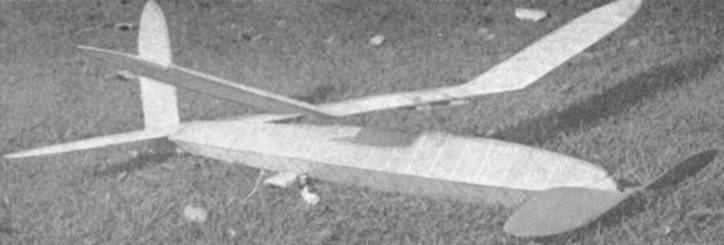
The "Favorite" employs a diamond fuselage and a parasol wing arrangement;
placed first, fourth, sixth, seventh, at the 1938 Nationals.
The Plan Page
[ Home ] [ Previous Plan Pages ]
[ Special Things ] [ Earl Stahl Plans ]
gt-hunter1@home.com
The
"Favorite" employs a diamond fuselage and a parasol wing arrangement;
placed first, fourth, sixth, seventh, at the 1938 Nationals.
THE AKRON FAVORITE
A trophy-winning stick model with an impressive
record earned at major contests.
by JACK SWARTZ
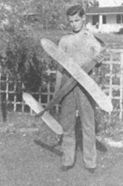
Jack Swartz and model. Design swept second,
fourth, eighth, at Junior Aviator Races.
DURING the 1938 contest season Akron contest fliers flew models of this design with exceptional success. The high places - first, fourth, sixth and seventh - which they won in the stick event, were responsible for the Akron delegation winning the Megow Trophy - an award made at the Nationals in 1938 for the most successful competing club. Later in the summer, models of this type again performed successfully. This time in Akron at the National Meet of the Junior Aviators of America it placed second, fourth and eighth. The durations of the flights ranged from well over ten minutes for first, six minutes, several five and four-minute flights, and a low of three minutes.
National Aeronautic Association rules for 1939 model flying have a change that is especially interesting to modelers flying a rubber powered model in the stick event. A stick model is defined : "A model of the stick type has a body composed of a single stick or open framework, rather than a fuselage. Models using tubes or a framework to enclose the motors shall have a total maximum cross-section area of stick not greater than L squared / 200, where L equals the length of the stick."
In previous years there was no ruling on the cross-section area of the stick. The result was that modelers were able to remove the landing gear of a fuselage model and fly it in the stick event. This year's ruling will prevent this. Stick models will have to be designed especially for this one event and converted fuselage models will be ruled out because of excessive cross-section area.
This model is eligible for contests under the new rules without any changes. The stick length is 39-1/2". This is the value of L. L squared equals 1560. Dividing by 200 equals 7.80, which is the maximum square inches of cross section allowed in this fuselage. Since the fuselage shape is a square with a maximum edge of 2-3/4", the cross-section area is 7.56 square inches - which brings the model within the ruling by .24 square inches.
The weight ruling for this type of model is the same as last year. The model must weigh at least 3 ounces for each 100 square inches of wing area. Wing area of the model is 197 square inches. Thus the required contest weight is practically 6 ounces. Ready-to-fly the model weighed 6.3 ounces - a safety margin of .3 ounces that won't impair the flying qualities and will make it easy for the contest officials to approve the model.
CONSTRUCTION
Stick or fuselage is square in cross section. It is set on edge for attaching the wings and tail. The side view of the model indicates the fuselage widths at the various stations along its length. These dimensions 1-5/8" at the front, 2-3/4" at the wing position, et cetera - are measured across the side of the square. The fuselage is first laid out in two halves as indicated by these dimensions and then joined. Build it the same as any square-sided fuselage. Check the square shape at all the cross braces.
Front and rear ends of the fuselage are filled in with 1/8" sheet balsa. The balsa should be cut to fit between the longerons and the cross braces and be flush with the outside edge of the longerons. (Pc. #2. )
Tail portion of the fuselage detaches from the main part at the first cross brace 2-11/16" from the rear end. A balsa plug (1/2 x 1-1/4 x 1-1/4 ", Pc. # 5) is cemented firmly inside the detachable tail portion - allowing about 3/8" of the plug to extend which fits into the rear of the fuselage. The nose plug is carved from a block 1-1/2 x 1-5/8 x 1-5/8", (Pc. #4). Carve 5/8" of the plug to a size that will just snugly fit inside the front of the fuselage. Both the front and rear plugs are held securely in the fuselage by rubber bands (Pc. #6) engaging small wire hooks (Pc. #7) cemented to the plug and the fuselage. No wire hook is necessary for the nosing since the rubber band fits into a groove carved into the nose block.
Rear hook is bent front 1/16" diameter wire (Pc. #13) and cemented securely to the rear plug. The end of the rear hook should be bent to fit around the main part of the hook and in this way prevent the rubber motor from slipping off when the rubber is wound.
Wing mount is made from two bamboo pieces (Pc. #3) mounted above the fuselage on two 1/16" diameter wire supports (Pc. #8). These supports are bent to an X shape with the top of the X closed. The bamboo members are cemented and threaded to each corner. The open, bottom part of the X fits across the top of the fuselage - thread and cement attachment to the cross bracing. The wing mounts should be set parallel to the center line. A convenient check in this case is to measure to the center longerons. The top of the bamboo pieces should be 1-9/16" above this longeron.
Propeller is carved from a medium-hard block 1-1/2 x 2 x 16" (Pc. #9). Camber the rear face of the propeller blades 1/8" at the widest portion, decreasing the amount of camber toward the tips. After sanding smooth finish the propeller with four coats of clear dope. Sand lightly after each coat.
Free wheeler is bent from 1/16" brass (Pc. # 11) to shape indicated in the drawing. It is securely attached to the propeller with the one prong inserted into the hub. Two small U-shaped bearings (Pc. # 10) are bent from sheet brass. Punch a hole through the bottom of each. One of them is pressed into the front of the nose plug. The second is pressed into the rear of the propeller. In both cases the holes in the hearings should line up with the holes already drilled through the propeller and the nose plug.
Assembly of the propeller and nose plug is done by first inserting the shaft (PC. #12) through the nose plug and bearing, adding 3 - 1/4" diameter copper washers. Insert the shaft through the propeller and bend a loop about 3/4" from the end of the shaft. This loop fits onto the winder, winding being done through the front of the fuselage.
Wing is made in three pieces. The center section is flat. The two outboard panels are cemented to the center section after construction has been practically completed with the exception of covering. All the wing spars are 1/16 x 16" (PC. #16). The spars are swept back at the tips.
Tips are 1/16" diameter reed (PC. #19) bent to shape and cemented firmly to the ends of the ribs and the spars. No wash-in or washout is used on the wing, so make sure it is perfectly flat throughout construction. Notice that the ribs at the end of the center section and the corresponding ribs on the outboard sections are staggered to fit snugly together when cemented at the correct dihedral.
Elevator construction is practically the same as the wing except it is flat through the span. In mounting the elevator to the detachable portion of the fuselage, cut away the top longeron and rest the elevator on side longerons. Cement.
Rudder is built to fit over the top of the elevator and up against the rear post of the detachable part of the fuselage. Rib shape similar to the elevator is used, the flat side being on the right side (top view). A piece of 1/8" sheet balsa (PC. #32) is cemented to the bottom of the fuselage and to the bottom of the rudder. Cement the elevator, rudder, and fuselage firmly.
Covering is with outdoor-type tissue. Stretch the tissue with water spray. The tissue on the fuselage is finished with four coats of a mixture of one half dope and one half thinner. Three coats of this mixture go on wing and tail.
Motor is eighteen strands of 3/16" brown rubber forty inches long. Lubricate the motor with prepared lubricant - usually for sale along with the rubber. Ordinary drugstore glycerin is an effective substitute lubricant. If you find more power is needed, boost the strands to twenty.
Balance the model at the center of the wing. If built according to the plans, the model should rest in a normal flying attitude when supported on your fingertips at the center of the wing. The wing mount is sufficiently long to accommodate fore or aft movement of the wing to take up any variations in weight from the original ship. No incidence is used on the wing - it rests flatly on the bamboo wing mounts. Slight offset thrust is used. A small 1/16" block is inserted between the nose plug and fuselage at the top left side.
Climb is steep and to the right. The glide is flat and fast. Adjustments are made by moving the wing. However, if slight forward or rearward movement does not correct the trouble, it may be advisable to add more downthrust. (Increase the size of block inserted between the nose plug and the fuselage.) If the model shows no tendency to climb, add a 1/16" sliver under the front of the wing. Good procedure in adjusting the model is first to get a smooth, flat glide. Any irregularities that turn up under power can be corrected by changing the thrust-line setting.
MATERIAL
(Material is balsa unless
otherwise noted. Where the same size stock
is used for several different items, the amount is grouped into one listing.)
Fuselage
| 10 pcs. | 1/8 x 1/8 x 36" (hard) | # 1 longerons and braces |
| 2 pcs. | 1/8 x 1-5/8 x 10" | #2 sheeting (front and rear) |
| 2 pcs | 1/16 x 1/4 x 7-3/4" bamboo | #3 wing mount |
| 1 pc. | 1-1/2 x 1‑5/8 x 1-5/8 " | #4 nose plug |
| 1 pc. | 1/2 x 1-1/4 x 1-1/4" | #5 tail plug |
| 2 rubber bands | #6 plug attachments | |
| 1 pc. | No. 6 (1/64" dia. x 6") piano wire | #7 attachment hooks |
| 3 pcs. | No. 26 (1/16" dia. x 13") | #8, #12, and #13 wing mount, shaft, rear hook |
| 1 pc. | 1‑1/2 x 2 x 16" | #9 propeller |
| 1 pc. | 1/16 x 1/4 x 3" brass strip | #10 and # 11 free wheeler, and bearings |
| 1 Ppc. | 1/16 " I. D. x 3" rubber tubing | # 14 rubber hook covering |
Wing
| 6 pcs. | 1/32 x 5/8 x 24" | # 15 ribs |
| 18 pcs. | 1/16 x 1/16 x 15" | # 16 spars |
| 3 pcs. | 1/8 x 1/8 x 13-1/2" | #17 leading edge |
| 3 pcs. | 1/8 x 3/8 x 13-1/2" | #18 trailing edge |
| 2 pcs. | 1/16 dia. x 12" reed | # 19 tips |
| 1 pc. | 1/8 x 3/8 x 1-1/2" | #20 reinforcements |
| 2 rubber bands | #21 attachment |
Elevator
| 5 pcs. | 1/32 x 3/8 x 12" | #22 ribs |
| 5 pcs. | 1/16 x 1/16 x 24" | #23 spars |
| 1 pc. | 1/8 x 1/8 x X21" | #24 leading edge |
| 1 pc. | 1/8 x 3/8 x 21" | #26 trailing edge |
| 2 pcs. | 1/16 dia. x 8" reed | # 26 tips |
Rudder
| 1 pc. | 1/16" dia. x 10" reed | #27 tip |
| 2 pcs. | 1/32 x 3/8 x 12" | #28 ribs |
| 5 pcs. | 1/16 x 1/16 x 10-1/2" | #29 spars |
| 1 pc. | 1/8 x 3/8 x 8" | #30 trailing edge |
| 1 pc. | 1/8 x 1/8 x 5" | # 31 leading edge |
| 1 pc. | 1/8 x 1-5/8 x 2-5/8" | #32 lower rudder |
Additional Item
| 3 sheets | outdoor tissue (21 x 31") |
| 2 ounces | dope |
| 70 feet | 3/16 " brown rubber |
| 3 washers | 1/32 x 1/4" O. D. |
| 1 ounce | thinner |
| 2 ounces | cement |
Scanned From June, 1939
Air Trails
![]()
![]()
[ Home ] [ Previous Plan Pages ] [ Special
Things ] [ Earl Stahl Plans ]