|
|
|
The Plan Page
[ Home ] [ Previous Plan Pages ]
[ Special Things ] [ Earl Stahl Plans ]
gt-hunter1@home.com
Building the Kinner Envoy
How You Can Construct a
Remarkable Flying Scale
Model of the Latest Transport Used by the U.S. Army
By STEPHEN J. GRAFFEO
|
|
|
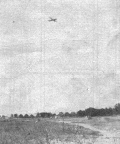
This ship is no slouch at climbing. Here it is in flight
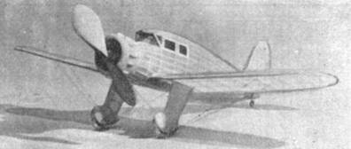
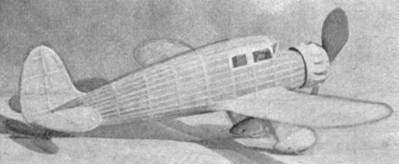
THE Kinner Envoy is a sensational new four-place cabin transport. It is powered with a C-7 300 hp. Kinner 7-cylinder radial engine, which pulls it at a maximum speed of 165 m.p.h. This plane is considered the last word in modern airplane design and construction, meeting the approval of the U.S. Navy which has invested in three Kinner Envoys for transportation of its personnel.
The model herein described, retains all the beautiful lines of its prototype and is an excellent flier, which is not usual for this type of model airplane.
Fuselage
First cut Plates No. 1 and No. 3 and join at A-A. Trace and cut upper and lower keels (1/16" x 3/16") from 1 /16" sheet balsa.
The bulkheads are cut to shape from 1/16" sheet balsa, as detailed in the plans, and notched for 1/16" square stringers. Cement bulkheads F, G, H, J, K, L, M, N, and O to upper and lower keels as shown on the plans. Check carefully front to rear for alignment, especially bulkheads G and J, otherwise the stub wings will not line up properly.
After cement has set, glue center side stringers in place, and when dry, glue in the remainder of the bulkheads. Be sure to make bulkhead E from 1/4" sheet balsa. Make rear hook from .029" music wire bent to shape shown and glued to bulkhead O. Cut former P from 1/16" sheet balsa to shape shown on Plate No. 5 then cement instrument panel to former P and cement in fuselage. Now cement all stringers (1/16" square balsa) in place.
Next make pilot's enclosure from soft balsa block 3/8" x 15/16" x 1-13/16", finish, and hollow out, then cement in proper place. Construct windshield from 1/16" square balsa strips glued to fuselage and pilot's enclosure as detailed on Plates No. 1 and No. 3.
Make front, center, and rear stub wing fillets from soft balsa as shown on Plates No. 1 and No. 3. Shape fillets so that they will match bulkheads G and J. Cement fillets to fuselage and allow to dry, then sand to a streamline shape.
Four pieces of .034" music wire are cut to required lengths and inserted into the center stub wings at the position detailed on the plan.
In covering fuselage, cover in sections; strips of tissue are cut as long as the distance between bulkheads. This is the only way in which it is possible to make a smooth covering job. Use banana oil or dope to cement tissue paper to fuselage. When completely covered, shrink tissue by spraying a light coat of water. When thoroughly dry, give two coats of clear dope.
Wings and Stub Wings
The wings are built in two separate panels, one right and one left. (Left wing panel shown on plan, Plate No. 5.) Make the right wing panel by tracing the left wing panel.
Cut 14 ribs from 1/32" sheet balsa and 6 ribs from 1/16" sheet balsa as detailed on Plate No. 5. Lay a sheet of waxpaper on the plan and pin front and rear spars in position. The ribs are now placed in their proper locations and glued. Slant rib A (1/16" sheet balsa) for correct dihedral angle. The leading and trailing edges are sanded to the shape shown and glued in place. Make wing tips as shown on drawings from 1/16" sheet balsa. This type of wing tip is recommended because it is easier to construct and gives a neater appearance. When the wing panels are completely dry, glue two pieces of 1/16" dia. aluminum tubing to front and rear spars as detailed on Plate No. 3 and No. 5.
To cover, use separate sheets of tissue. Cover tops of wing panel first, and then the bottom. Use banana oil or dope to cement paper to wings. Shrink and dope wings in the same manner as fuselage.
Use the same procedure as for the wing; above in making the stub wings, and before covering them, cement .034" music wire to front and rear spars as detailed on Plate No. 2. Now glue stub wings to fillets and bulkheads G and J, and then cover.
Motor Cowl and Dummy Motor
Make cowling front Z by laminating two 1/4" sheets cross grain to avoid splitting when carving. Carve and sand to shape as shown on Plate No. 2. Next carve and sand rear cowling bulkhead W from 1/4" sheet balsa. Before assembling the motor cowl, make the crankcase from a 1" x 1" x 1-3/4" balsa block, and cement to bulkhead W. Now cut out seven celluloid cylinders from a standard 3‑inch celluloid dummy motor, and glue the cylinders to the crankcase as detailed on Plate No. 1. Then cover the rear part of the cowling with 1/32" sheet balsa. This completes the cowling and dummy motor, with the exception of the fourteen valve covers which are glued around the outside of the cowling as detailed on Plates No. 1, No. 2 and No. 3. The motor cowl with the crankcase and dummy motor is detachable to permit the use of a mechanical winder.
Landing Gear and Tail Wheel
The streamline wheel pants are cut to shape and built up in three sections as detailed on Plates No. 1 and No. 3. Carefully carve and sand to a streamline shape so that they may be glued to the built-up landing gear struts. Now make the landing gear struts as shown on Plate No. 1. Be sure to streamline struts before cementing to landing gear fillet X (Plate No. 4), which is also carved and sanded to a streamline shape. When dry, cover the landing gear struts with tissue. Spray with water and dope. Now assemble the landing gear and cement it to the wing stubs, and allow to dry.
Make tail wheel assembly as detailed on plan (Plate No. 3).
Tail Surfaces
Pin a 1/16" x 1/8" balsa spar to the drawing; cut out the leading and trailing edges from 1/16" sheet balsa for the stabilizer. Cement 1/16" x 1/8" ribs as shown on Plate No. 4. Make the rudder in the same manner. When dry, taper the ribs from the spar toward the leading and trailing edges. Cover the tail surfaces in the same manner as the wing panels. Spray lightly with water and dope.
NOTE: After the tail surfaces and wing panels are sprayed with water, lay them on a flat board, and place weights along their outline to keep them flat against the board to prevent warping.
Propeller and Motor
Make the propeller from a 7/8" x 1-1/4" x 8" block of medium balsa, cut to shape shown, then carve and sand prop in the usual manner. Dope the finished prop two or three times, sanding between each coat to ensure proper balance of the prop.
The scale propeller is clearly shown on plan (Plate No. 4).
The prop. shaft is bent from .029" music wire. It is inserted through the crankcase, washers and propeller, and then bent over and sunk into the front face of the propeller hub, where it is cemented.
Power the model with six strands of flat brown rubber.
Assembly
Cement the tail surfaces on to fuselage, being sure to get the correct stabilizer setting. Next assemble the wings to the stub wings. For all bracing, flying and landing wires, use strong black silk thread. All other details are shown clearly on the drawings.
Flying
Glide the model over tall grass before it is flown. If the plane is tail-heavy, add some weight to the nose until you get an even glide. You can now wind the propeller for a test flight. Any adjustments regarding the flight of the model after it is carefully balanced may be made by adjusting the stabilizer setting. If the model is correctly built, you will be able to obtain flights of one hundred to three hundred feet.
Bill of Materials
|
3 |
1/16"x3"x18" sheet balsa |
Bulkheads, keels, ribs, wing, stabilizer and rudder tips. |
|
2 |
1/32"x2"x18" sheet balsa |
Ribs and motor cowl. |
|
26 |
1/16" square x 18" balsa strips |
Stringers and windshield. |
|
2 |
1/8" square x 18" balsa strips |
Leading edges. |
|
2 |
1/16"x3/16"x18" balsa strips |
Trailing edges. |
|
4 |
1/16"x1/4"x18" balsa strips |
Wing spars and trailing edges of landing gear struts. |
|
1 |
1/4"x3 "x18" sheet balsa |
Cowling bulkheads and landing gear fillets. |
|
1 |
3/16"x2"x9" sheet balsa |
Wheel pant sides and leading edges of landing gear struts. |
|
1 |
1/8"x3/16"x18" balsa strip |
Valve covers. |
|
3 |
1/16"x1/8"x18" balsa strips |
Tail surfaces. |
|
1 |
3/8"x15/16"x1-13/16" soft balsa block |
Pilot's enclosure. |
|
2 |
7/8"xl"x2-9/16" balsa blocks |
Center stub wing filets. |
|
2 |
11 /16x11/16"x15/16" balsa blocks |
Front stub wing fillets. |
|
2 |
11/16"x15/16"x2-3/8" balsa blocks |
Rear stub wing filets. |
|
1 |
3/8" x2"x5‑3/4" sheet balsa |
Wheel pants center section. |
|
12" |
.029" music wire. |
|
|
8" |
.034" music wire. |
|
|
4 |
1/8" brass washers. |
|
|
1 oz. |
cement. |
|
|
2 oz. |
clear dope. |
|
|
1 |
1"x1"x1-3/4" balsa block |
Crankcase. |
|
2 sheets |
tissue paper |
|
|
1 sheet |
cellophane. |
|
|
6" |
1/l6" dia. aluminum tubing. |
|
|
1 |
3" standard celluloid motor |
Cylinders. |
|
1 |
1/2" dia. balsa tail wheel. |
|
|
1 pair |
1-1/4" wheels‑balsa or celluloid. |
|
|
6 ft |
1/8" flat brown rubber. |
|
Scanned From October 1935
Model Airplane News
![]()
![]()
![]()
![]()
![]()
[ Home ] [ Previous Plan Pages ] [ Special
Things ] [ Earl Stahl Plans ]