|
|
|
|
The Plan Page
[ Home ] [ Previous Plan Pages ]
[ Special Things ] [ Earl Stahl Plans ]
gt-hunter1@home.com
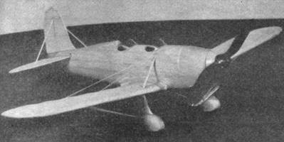
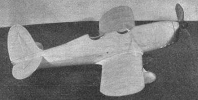
Build and Fly This Ryan "Low Wing"
How You Can Build a Model
With a Unique All-Balsa
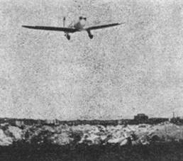
Monocoque Fuselage That Has Unusual Flying Ability
By JESSE DAVIDSON
|
|
|
|
A WIDESPREAD misconception prevails that the hollowed out type of fuselage is difficult to build. The only way to dispel such an erroneous impression is to prove to you with clear and simple instructions the ease with which it can be built.
Reading these instructions may cause the impression that the scooping of the fuselage is a tedious process. But a job is tedious only to one who lacks a patient temperament. Plunging into the job is the only means of refuting your own impression.
To the model builder who has heretofore built stick models perhaps the foregoing leaves more to be desired. But what greater assurance can there be for the child first learning to walk than a steadying hand to instill confidence? Likewise the steadying hand in your case is your own confidence and the faith in your skill.
A few words about the Ryan S-T will interest you. It is manufactured in San Diego, California, by the same company that built Lindbergh's "Spirit of St. Louis." With its eighteen miles per gallon of gas, its long-lived engine and durable metal construction, this ship compares favorably in cost and operation with that of the average priced automobile. Built with an extraordinary degree of inherent stability, the Ryan S-T has been flown hands and feet off the controls for several hours, proving that cross‑country flights can be made with complete comfort and a minimum of fatigue.
Wing flaps, which are standard equipment, reduce the landing speed by ten miles per hour. Trimming tabs situated at the rear of the elevators are also standard equipment. This modern addition dispenses with the old adjustable stabilizer which caused tail flutter in high speed jobs. The new method gives more accurate adjustment and is controlled from the cockpit thus making possible the rigid stabilizer such as is used on the multi‑motored transports today.
Materials
Following is a list of materials which should be on hand
before starting construction of your model:
Fuselage
2 blocks, 3/4" x 2-1/4" x 12-1/16".
Sheet balsa
1/16" flat, for wing ribs and tail frames.
Balsa strips
1/16" sq. for rudder and elevator ribs.
Nose plug
1 piece, 11/16" x 1-1/8" x 1-3/4"
Tail plug
1 piece, 5/8" x 1-1/32" x 1-5/16".
Wing stubs
2 pieces, 9/16" x 1" x 4-1/8"
Landing struts
2 pieces, 1/8" x 1-5/32" x 2 -1/8 "
Wheel pants
4 pieces, 5/16" x 7/8" x 2-5/16".
Propeller block
5/8" x 1" x 6-1/2".
Leading edge spars
2 strips, 3/16" x 1/4 " x 8-3/16".
Front spars
2 strips, 1/16" x 1/8" x 8-15/16".
Rear spars
2 strips, 1/16" x 1/8" x 8-3/4".
Trailing edge spars
2 strips, 1/16" x 3/16" x 7-1/4".
Strip of bamboo for wing tips
1/32" sq. x 12".
Prop spinner block
1 piece, 5/8" sq.
Wing struts (A)
2 strips 1/16" x 1/8" x 1-11/16".
Headrest block
1 piece, 1/4" x 3/8" x 2-1/16".
Tailwheel
1/2" diameter.
1 pair of balsa or celluloid wheels
5/16" x 1" diameter
Celluloid for windshields, brass eyelet, music wire for hooks, strong white thread for landing and flying wires, colorless cement, best jap tissue, banana oil, sandpaper and a little ambition.
Fuselage
As a beginning, the Ryan S-T is one of the best types of planes to use in the flying scale model phase of building. The hollowed-out type of balsa fuselage was used to simulate the metal covering of the real ship.
The blocks for the fuselage should be clear grained and soft. Spread cement thinly along the insides of each half and lightly press both together, placing it under a weighted object and allowing an hour or two to dry. During this time, cut out the templates or patterns of the sides and top view of the body. This is done by taking sheets Nos. 1 and 2, fitting them together and pinning them down flat on your work‑bench. Lay over these pages a sheet of tracing paper and trace carefully. Afterward, darken the opposite sides of the tracing paper with pencil lines. Retrace again on any flexible cardboard or stiff paper and cut out. You will need one pattern of the top view and one of the side view. Next lay the pattern of the side view on the block and trace its outlines. This is done on both sides always to insure accuracy. Using a sharp knife, carefully cut down to about 1/16" near the lines. Employ a medium grade sandpaper the rest of the way. The next step is to trace the top view. This is also done on the bottom of the block. Cut to shape. Now your fuselage begins to take form.
On sheet No. 4 you will notice the body sections lettered A, B, C and D. By making a tracing of each and cutting them out of stiff paper you will see how these patterns are to be used. Your fuselage block must, of course, be flat at both ends. Now take section lettered A. This is placed directly against the nose end of the block and one-half of the oval shape is traced on that half of the block. Turn the pattern over and do likewise to the other half of the block. Now you have a perfect oval shape or monocoque design.
The same is done on the tail end of the body with pattern lettered D. Proceed, now, to carefully cut the fuselage to form, working from nose to tail. When the body begins to take the oval form more conspicuously, take pattern lettered B-C and place flush against the sides of the body at points shown on the plans in the top view. Hold the body up to the light with the pattern at its designated point and, if no light passes between the outside form of the fuselage and the inside curve of the pattern, then you know the shape of the body is correct. Check on both sides of the fuselage on this. Finish by sanding smoothly.
The next step is to separate the blocks carefully and this is done with a razor blade. Do not use a knife. Again make another template or pattern for the inside of the fuselage which you will note is 1/16" less all around except near the nose and the tail ends. By laying this pattern flat against the inner sides of each half of the block and drawing its outline you will have the area marked for the hollowing or gouging.
Use a very sharp 3/8" gouge. The ease of the job, of course, depends on the sharpness of the tool. It is a good idea to have a sharpening stone handy, if necessary, to sharpen the tool. The walls are cut to a depth of 1/16" all around except near the nose and tail end. Do the job carefully and take your time. You'll get through with it soon enough. By holding each shell against a bright light you will be able to detect any thick parts which should be sanded or cut down as to shape. Use smooth sandpaper and clean out the shells thoroughly. The next step is to cement both halves firmly together. If you have any half inch ribbon handy, wrap it around the fuselage to insure a vise-like grip. Rubber bands placed at intervals will also do the same thing.
When the fuselage has dried thoroughly, give it a soaking coat of banana oil. This will raise the grain a little, after which it will sand down smoothly.
At this time it is best to shape out the removable nose and tail plugs. Each of these are made in one piece. They conform with the shape of the body. Cement a brass eyelet bearing in the center of the nose plug and drill the hole for the prop shaft. A wire hook is cemented in the position shown on sheet No. 2 to the rear plug. Fit both parts in their respective places and sand again to insure perfect form. Be sure that the plugs work freely.
Wings and Tail Surfaces
The first step in making the wings is to make a tracing of the wing shown on sheet No. 3. Turn this tracing over on its back and pin down to the bench. If you do not wish to destroy the page of the magazine make a tracing for each half. The ribs for the wings are cut from 1/16" thickness sheet balsa. Fourteen No. 1 ribs and two No. 2 ribs will be needed. To assemble a wing panel, first pin down the trailing edge spar and the rear wing spar. Apply cement at the rear ends of each rib and in the rear spar holes. Fit the rib into the spar and place flush against the trailing edge spar at the same time. Care must be taken to place each rib in its exact position as shown, on the plans to insure balanced wings.
Next, apply cement in the front spar holes and place the front spar in. This is followed by cementing the leading edge spar in position. This spar must first be shaped to conform with the curvature of the wing rib as shown in the drawings. Bamboo bent over the candle flame is shaped to fit the rounded wing tip. Make both halves alike.
Wing Stubs
The wing stubs are made in halves from soft clear grained balsa. Sheet No. 4 shows front, side and top views of this part. It is very important that the inner cut-away portion is made just right. Both parts must be exact. When you have completed them, apply cement liberally and set each flush against the sides of the fuselage in the position shown on sheets Nos. 1 and 4. Cemented thusly, the wings automatically assume the proper dihedral angle when they are attached to the stubs.
Tail Surfaces
The elevator is made in halves. The outline frames are cut from 1/16" flat. The ribs are 1/16" sq. The spar is 1/6" flat. Note the direction of the grain of each piece that forms the frame of the elevator. Round off the leading edges and taper the trailing edges. The rudder is made of the same material and in the same manner.
Landing Gear and Parts
The wheel pants are made in halves. Before cementing together, insert the wheel. Use pins for axles and be sure the wheels roll freely. See details on sheets Nos. 1 and 4. The prop is carved from a block of hard balsa wood to the design shown on sheet No. 3. Carefully balance it, insert the wire shaft and, after slipping it through the nose plug, turn up the end as illustrated in sheet No. 1. A brass washer or two may be used. Use celluloid for the windshields, cut to the designs shown.
Covering
Cover each part of the wings first. Use the best grade jap tissue available and light banana oil for the adhesive. Pull paper tightly to remove the wrinkles. When covering a wing with a round wing tip such as used on this Ryan model, cover as far as the last rib. From there, use a separate piece of paper between that rib and the tip. This makes a much neater job at the tips as otherwise many wrinkles occur that even doping will not remove. The tail surfaces are covered on both sides.
Spray all the paper covered parts lightly on both sides with an ordinary house hold atomizer filled with water. It is best to place objects of medium weight on the tips of the tail parts to keep them from warping. It is not necessary to dope the wings or tail for flying use. It is done only as a preparatory coat for lacquer or colored dopes.
Assembly
A simple way to assemble this ship is to first lay each half wing on its back. Take the landing gear part which is composed of the landing struts already cemented to the wheel pants and cement it flush to the wing wheel facing upward. Use a few small pins to hold in place temporarily. Of course, this is done to the other half wing too. Allow time to dry. Now liberally apply cement along the first rib and the wing stub and firmly press the wing to the stubs at the same time inserting a couple of pins to hold securely. This done attach the other half wing in the same manner. Check on dihedral angle. See sheet No. 4. Attach strut lettered A as shown.
The elevators are cemented in the position shown. Use a small pin to hold securely so that they will not droop while in the process of drying. Later remove all pins. Attach the rudder in place and check for alignment. Four exhaust pipes 1/8" dia. x 3/16" long are cemented to the lower right hand side of the motor cowling. Touch these up with black paint. Four to six strands of 1/8" flat rubber are sufficient to fly this model. Glide the model several times without power to observe the best gliding angle. For longer flight, use a gear winder. Always launch your model into the wind.
Paint job
It is not necessary to paint the model. The extra weight will detract from its flying qualities. However, when you have decided to end its flying days, pension it with an attractive paint job. On sheet No. 5 (there was no sheet 5 in the magazine) will be found this attractive color scheme. The three view drawing also serves to show the position of the landing and flying wires as well as the tail braces.
Scanned From January 1936
Model Airplane News
![]()
![]()
![]()
![]()
[ Home ] [ Previous Plan Pages ] [ Special
Things ] [ Earl Stahl Plans ]