|
|
|
The Plan Page
[ Home ] [ Previous Plan Pages ]
[ Special Things ] [ Earl Stahl Plans ]
gt-hunter1@home.com
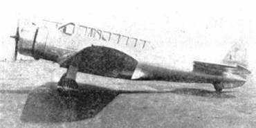
A Flying Scale Model of Vultee
V-11 Attack Bomber
We are presenting in this
article the construction
of a model of the latest and fastest type of
attack planes in use by any nation in the world.
by Harry S. Pack, Jr.
|
|
|
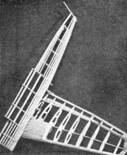
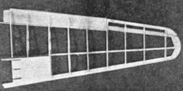
Half shell of Vultee fuselage.
Note wing flap in "down" position.
THE Vultee Attack Plane has exceeded the performance expected by its designers and Gerald Vultee of the Airplane Development Corp. (a Cord subsidiary) of Glendale, California, after whom it was named.
Much of the structural features of this plane has already been proved in the high speed V-IA ten-passenger airline transport of the same name. With the exception of the fabric covering on the elevator and aileron surfaces, the plane is of all metal construction.
Extensive tests have been run on the second of these planes off the production line and it has shown a cruising speed of 220 miles per hour and a top speed of 245 miles per hour at an altitude of 16,000 ft.
Powered with the new Wright "Cyclone" Model SR-1820-F53 which delivers 750 horsepower at 16,000 ft., the Vultee will climb to 20,000 ft. in 14 min. It has a service ceiling of 27,000 ft., and an absolute ceiling of 29,500 ft.
The plane presents quite an interesting appearance with the high location on the fuselage of the stabilizer-elevator units on the top of the fuselage and forward of the rudder post. This unique arrangement gives the machine gunner an exceptionally wide range of fire.
The "hot-house" or pilot and gunner location on the top of the fuselage adds to the interesting appearance of the plane - no doubt to the drag also.
Loaded for attack with 600 pounds of ammunition, the V-11 has a range of 2200 miles. In an overloaded condition with 1200 pounds of bombs, it has a range of 900 miles. Internal racks with stainless steel chutes are provided for twenty 30 pound bombs. Fully loaded with external bombs, the cruising speed is cut down about 25 miles per hour.
Many other good constructional and aerodynamical features tend to make the V-11 one of the outstanding military planes of the world. Due to the large plane's good aerodynamical qualities, the flying scale model of it described here is one of the best low wing models we have seen. It is fast and stable in flight and if built of light balsa will fly quite a distance.
Constructing the Model
In order to construct a flying model of the Vultee Attack plane, it is first necessary to study all pages of drawings carefully. They are numbered so you can cut them out and use as sets. Pin to work bench or drawing board and place wax paper over them.
The following is a list of some of the standard wood thicknesses used in this model:
Wing ribs No. 1 to No. 4 are 1/16-in. thick Wing ribs No. 5 to No. 9 are 1/32-in. thick Most of the longitudinal stringers are 1/32-in. x 1/8-in. Main wing spar is 1/16-in. thick Auxiliary wing spars and ailerons are 1/32-in. thick Stabilizer spar is 1/32-in. thick Stabilizer, elevator, fin and rudder ribs are 1/32-in. thick All tip or shape formers, wing, stabilizer, rudder and fin are 1/32-in. thick. Bulkheads 2A, 2B, 3A, 3B, 5, 6, 7, 8, 9, 10, 11, 12 and 13 are 1/16-in. thick Bulkheads 1, 4A and 4B are 1/32-in. thick N.A.C.A. cowl is covered with 1/64-inch sheet balsa Flap is 1/64-inch sheet balsa Keel pieces should be cut from flat sheet 1/32-inch thick Skin (covering), upper and lower surface of the wing between fibs 1 and 3 from leading edge to main spar (retractable landing gear location), is 1/64-inch thick. In building this model it would be advisable to start with the fuselage. Lay out pages one and three so the fuselage lines meet at the vertical border line. Cut two pieces from flat sheet for top and bottom keel pieces. Grained markings on drawing show shape and location of these. Place wax paper over drawing and pin keel pieces in place. Next cut out bulkheads 3A to 13 and assemble on keel pieces, pin in place, put in a stringer in notches half-way between top and bottom of bulkhead, line up bulkheads and cement at keel pieces and stringer. Allow to dry, then add rest of stringers and cement. Make other half of fuselage by tracing outline from Figs. 1 and 3 and reversing tracing on board. Assemble in same manner.
Construction of Wings, Etc.
Using rib templates, cut out two ribs for each template. Cut out wing spar according to view of same on Figs. 4 and 5. Using Figs. 2 and 7 assemble ribs on main auxiliary and aileron spars. Line up and cement in place. Put in leading edge stiffener and leading and trailing edge members. Assemble aileron on drawing. Flap should be cut from 1/64-inch sheet balsa shown on plan. Trace wing assembly and reverse tracing. Assemble right half of wing on this reversed plan. Cement the two halves of the fuselage together. Giving wing proper dihedral angle, cement two halves in fuselage.
Assemble rudder and fin on drawing. Cement fin to fuselage.
Make stabilizer and elevators in same manner as wing. Cement stabilizer to fuselage in proper position.
Using thin aluminum pieces ; 1/8-inch x 3/8-inch for hinges, for ailerons, rudder, elevators and flap - join to fuselage with cement.
The Landing Gear
Landing gear in order to function properly must be very accurate, so measure "leg" from side view and cut out two. Cut two circular pieces froth sheet balsa, cut into two pieces as marked on side view and using tissue and cement rolled on .030 wire or a pin as a hinge, carefully cement together. Then cement to leg. Wire push rod must be exact length shown in front view. Using same type of hinges, assemble leg and push rod to rib No. 3. Push rod should be on small block at upper end to make it function properly, i.e., when the leg is pushed into the wing, rod should act differentially and make small cover plate come up flush with wing. Adjust until mechanism functions properly. Make two small chips to hold axle and keep under‑carriage from dropping down again. On the front view a small brace is shown for landing gear in down position. Make and cement in place shown.
Cowling, Propeller, Etc.
N.A.C.A. cowl should be built as one unit by assembling on top of bulkheads 2A and 2B. Motor stick should be cemented in position shown on side view.
Propeller should be made of hard balsa blades cut from blocks three-quarters of an inch thick and according to pattern shown. Thickness pattern is incorrect in that it is the wrong thickness, but tapering should be same on your prop. Assemble three blades, dope and sandpaper. Push pin in for prop shaft hole. Make shaft and bend as shown.
Washers should be used on nose both sides of main wheels and tail wheel.
After assembly of wing and fuselage, the filleting should be completed, Forward of the wing spar should be filleted with light, soft balsa block; cemented in place and sanded to shape Aft of the spar the 1/16 sq. notches in the bulkheads will locate the 1/16 sq. stringers.
The next step is to cover the model with colored tissue. The fuselage filleting and fin should be blue; the wing, stabilizer, elevators and rudder should be orange.
Covering
Cover fuselage with small sections of tissue - use any good grade dope or banana oil for fastening. Wing should be covered in one piece for top and bottom surface of each wing. Stabilizer should be covered a half at a time; elevators one side at a time. Dope all edges and trim with sandpaper.
Front windshield, rear windshield and center of "hot-house" should he covered with .050 celluloid sleet cemented in place. Strips of black tissue call be used to simulate divisions in the "hot-house".
Prop should he doped aluminum.
Power and Testing
When model is finished and dry, prepare six strands of 1/8 x 1/32 rubber and assemble motor unit of prop. washers, cowl, motor and motor stick.
Model should balance at the wing spar. If tail heavy, add small weight inside N.A.C.A. If nose heavy, add inside tail wheel housing.
When balanced, try a few glides and adjust ailerons for lateral trim and elevators and rudder for longitudinal trim.
Next try a few winds for trial flight - either with landing gear down or up. When really adjusted wind either by hand or winder several hundred turns and permit to take-off or hand launch.
Much interesting data call be gathered from experiments with flaps down and in different positions. Also, with surfaces in various positions.
Scanned From April 1936
Model Aircraft Builder
![]()
![]()
![]()
![]()
![]()
![]()
![]()
![]()
[ Home ] [ Previous Plan Pages ] [ Special
Things ] [ Earl Stahl Plans ]