|
|
|
The Plan Page
[ Home ] [ Previous Plan Pages ]
[ Special Things ] [ Earl Stahl Plans ]
gt-hunter1@home.com
The Consolidated P‑30 Model
by
PAUL W. LINDBERG
Model Editor and Designer for
POPULAR AVIATION
|
|
|
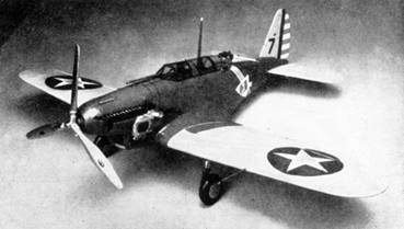
THE Consolidated Model P‑30 is the latest of designs. Many refinements have been incorporated in the construction of this marvelous little pursuit ship. We advise you to take your time in building this model and you will be well repaid for your efforts.
In undergoing experimental flights, our laboratory found it to be an excellent flyer. Please note the great amount of detail built into this model, such as supercharger, the machine guns both front and rear, the sight and all other parts that make it an exhibition as well as a flying model.
All controls are movable with aluminum hinges. False ribs are used in the panels where necessary. If you wish a larger model, multiply these measurements by the required ratio of increase. The color scheme can be obtained from the cover of this issue.
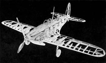
CONSTRUCTION OF FUSELAGE
It is necessary to place a sheet of ordinary wax paper over the plan to prevent cement from sticking to the plan. In building the fuselage, construct one side at a time. The longerons, vertical and diagonal braces, etc., are held in place until securely cemented by inserting straight pins on either side of strips.
After the two fuselage sides are completed they are pinned to top view of the plan in such a manner that the top longerons face down and the sides are at right angles with the table. The cross‑members are now cemented in place forming a rectangular fuselage. The formers are now applied to the framework. Trace these from the plan on the 1/32‑inch sheet balsa and carefully cut out with a razor blade.
The nose piece, having a 1/4‑inch hole drilled through it, is next cut and shaped as shown on the plan. After properly carving and sanding, it is cemented securely to nose of fuselage. The rear streamline balsa tail piece is now carved, sanded to shape and cemented to rear of fuselage.
The formers are then cemented into the position designated in top and side views of fuselage by corresponding identification numbers. The 1/32 x 1/16‑inch balsa fairing strips are cemented into position working from front to rear. Notch only Former 1. On the rest of the formers, the stringers are carried over outer edges to prevent bulkheads from projecting through tissue when covered.
A very stiff grade of paper is used in covering the following spaces: top between rear of nose and Former 2, the sides of motor cowl, radiator and under sides of nose between nose block and radiator. A piece is also used on either side of body working from Former 7 toward Former 8, this is necessary to receive balsa fillet which is cemented in at this location. A long, narrow piece of stiff paper is used for cockpit enclosure, extending from Former 2 to balsa block at rear machine gun mount. Make small arches above cockpit of same material.
CONSTRUCTION OF WING
Construct each wing panel separately, left and right, for when they are finished they must be blocked up to the proper dihedral angle. Make both leading edges from 1/8 x 3/8‑inch balsa. The trailing edges are made from 1/16 x 1/8-inch balsa, carve and sand these to their proper shape.
Lay a sheet of wax paper on plan and pin center spar into position. Cut ribs from 1/32‑inch sheet balsa, they are next placed into position at a slight angle (to account for dihedral) and are cemented. The leading and trailing edges are now cemented into place. Use pins wherever needed in holding ribs, etc., in position. The wing tips are made from 1/16‑inch thick balsa. Place all braces in wings, etc., as shown on plan, as this eliminates warping the framework when being doped.
ELEVATOR
Cut the ribs from 1/32‑inch sheet balsa and pin in an upright position, the spars are made and cemented to the ribs at their proper locations, the spars are tapered from tip to tip. See plan. The leading edge of elevator is made from 1/16‑inch square balsa, the trailing edge is made from 1/16‑inch sheet balsa, tapering same off at rear. Tips of elevator are cut from 1/16‑inch sheet balsa.
RUDDER
The rudder is very simple to construct, as it has no streamline section, being made chiefly of 1/16‑inch square and sheet balsa. Braces are 1/32x1/16-inch strips.
FRAMEWORK ASSEMBLY
Place both wing panels on a flat surface and raise either end to the proper angle as shown on plan. Cement the leading edge and spar securely at center.
Next place the completed framework of fuselage over wing panel using a 1/16‑inch balsa block to separate leading edge from Former 7. Apply cement to the various points of connection and let stand until dry. The trailing edge at ribs "A" is broken and cemented in a straight line between these ribs. This is to prevent a hump in fairing on under side of fuselage when covered. It will be necessary to place only a small block between bottom stringer and trailing edge.
The front fillets between ribs "A" and sides of fuselage are cut to outline shape and cemented securely in position. After they have become thoroughly dry roll a piece of sand paper so that it forms a cylinder, that is used in sanding to the required shape. The remaining fillet formers are cut from 1/16‑inch sheet balsa and cemented into position. Balsa wood fillets are carved and sanded and cemented to elevator and rudder ends, which in turn are cemented to fuselage, after same has been completely covered and doped.
LANDING GEAR
Make landing gear struts from a hard grade of balsa, having been sanded round in shape, paper is wrapped around to represent offsets and struts. Notch strut at top and cement to rib B. 1/16‑inch sheet balsa is cemented between ribs C and B ‑ H and B at bottoms to reinforce landing gear strut. Please note the 1/8‑inch square balsa diagonal braces.
The wheels may be built up of 1/8-inch flat stock or these may be substituted for 1-1/2‑inch aluminum wheels.
COVERING THE MODEL
In covering the fuselage, cover it in strips, one to two fairings in width on the top and bottom sides. On the sides, the strips may be wider owing to the flatter surface. On our experimental model, we covered each space separately. The wing panels may now be covered. Cover same from rib "A" out toward tips. The coverings of the wings, upper and lower sides need not be fastened to each rib, but only to rib "A" wing tips, leading and trailing edges.
The elevator and rudder are covered on both sides in very much the same manner as wings.
Using a small water color brush, give the entire fuselage, wings, etc., a light application of water. This will cause paper to tighten, smoothing out all wrinkles. After the tissue has become taut, give surfaces a coat of clear dope. Tissue paper may next be applied to fillets where wing joins fuselage. Cover each space separately, for instance: the space between front balsa fillet and 21, ‑21 and 22, etc. Shrink and dope in same manner as other parts. All aluminum hinges being cut from flat sheet aluminum are next cemented in their respective positions, after first slotting aileron, rudder, elevator to receive hinges.
After the ship has been completely covered and doped, the details for supercharger, etc., may be worked in. In building the exhaust, construct one long exhaust pipe for either side. To this, attach short pieces of balsa to represent stacks. They number twelve to each side. Any cracks, etc., may be filled in with cement as this will add to the appearance when painted.
The supercharger is built up in separate pieces, the round drum first, with other little fittings attached to it later.
END
Scanned From October,1934
Popular Aviation
![]()
![]()
![]()
![]()
[ Home ] [ Previous Plan Pages ] [ Special
Things ] [ Earl Stahl Plans ]