|
|
|
The Plan Page
[ Home ] [ Previous Plan Pages ]
[ Special Things ] [ Earl Stahl Plans ]
gt-hunter1@home.com
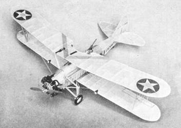
Building the Martin Dive‑Bomber
by
PAUL W. LINDBERG
Model Editor and Designer
for POPULAR AVIATION
|
|
|
THIS particular model makes an excellent flyer and carries all of the latest improvements. The model is Type BM‑2 and can be built with or without the ring cowl. It is equipped with movable controls which carry aluminum hinges. We advise you to build the model with movable controls, because this is an excellent method of controlling the flights of your model.
COLOR SCHEME
Fuselage‑silver with red band around fuselage behind gunner's cockpit.
Ring cowl and Motor plate‑red.
Wings‑lower panels all silver; top side of top panel‑Navy yellow; lower side of top panel‑silver.
Tail surfaces‑yellow.
Details‑black and silver.
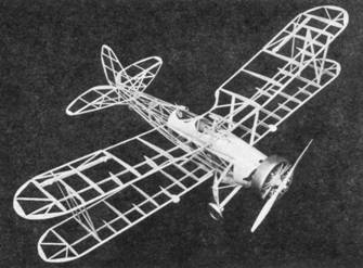
CONSTRUCTION OF FUSELAGE
First, place waxed paper on top of plan to prevent parts from sticking to it. The fuselage sides are built from 1/16-inch square balsa. The longerons, verticals, diagonal braces, etc., are held in place until securely cemented by inserting straight pins on either side of strips wherever needed. When the two sides are completed, the crossmembers are cemented into their proper locations. Check carefully front to rear for alignment.
Cut the formers from 1/32‑inch sheet balsa and cement in their respective positions as shown on the plan. The position of all stringers are clearly shown on the formers. See plan. Work stringers from front to rear and check carefully to see that they have the correct spacing. Stiff paper is required between nose block and formers 1. 7 and 13; also between formers 1, 2, 3 and 4.
CONSTRUCTION OF MOTOR
To form cylinders, wind heavy thread around balsa blocks which have been cut and sanded to shape. The crankcase is made from two separate blocks. Rocker‑arm, housings and pushrods are also made of balsa. Details of these parts are clearly shown on plan.
CONSTRUCTION OF WINGS
Cut all ribs from 1/32‑inch balsa. Pin the spar in position on the plan. Now, cement ribs in their proper locations. The leading and trailing edges are cut and sanded to shape and cemented to the ribs. The panels carry movable ailerons which are a great help in controlling the flights. Make wing tips from 1/16‑inch thick balsa. We highly approve of this type of wing tip, because it is much easier to construct and neater in appearance.
ELEVATOR AND RUDDER
These are built from 1/16-inch square and flat balsa, and are constructed on the plan. Their construction is very simple, therefore, no difficulty should be encountered here.
LANDING GEAR
To permit bomb to be carried on the under side of fuselage between the landing gear struts, the construction of landing gear differs from the ordinary landing gear. To assure strong landing gears. it is very important that they are reinforced with piano wire.
BOMB AND BOMBRACK
The front and rear of bomb are made from two blocks of balsa. The space between these blocks is covered with stiff paper. The fins are also made of stiff paper and reinforced with piano wire. The bombrack is made from two pieces of 1/8‑inch square balsa which are rounded to correct shape. The ends of bombrack are slotted to receive piano wire which passes through center of bomb.
COVERING THE MODEL
Apply tissue to the various framework members, using a light grade of model airplane dope to fasten it to the outer edges. Stretch tissue as tightly as possible to remove all wrinkles. When edges have dried, apply coat of water to tissue. When all water has dried completely, tissue will become taut. May we suggest that you pin wings, elevator and such up a flat surface to keep from warping.
ASSEMBLY
The landing gear can be cemented to position. The lower wing panels, which carry pins at the roots, may be inserted into balsa wing beam supports which pass through bottom of fuselage. Next, cement top wing in place together with the outer and center struts. The elevator and rudder can now be cemented to rear of fuselage. All other details, shown on plan, can now be applied.
The machine gun is built from separate pieces of balsa, and no trouble should result here. With an ordinary needle and thread, all flying and brace wires are easily installed. Please keep in mind, that it is the details which add to the appearance of the model.
TESTING AND FLYING
Two types of propellers are used on this model. One is made of filler which has a much wider blade in order that the rubber motor will turn at less r.p.m. enabling the model to fly a greater distance. By twisting the blades, the pitch can easily be adjusted. The balsa scale propellor is used for exhibition purposes only. Six strands of 1/8 flat rubber are sufficient to fly the model.
With the rubber motor and flying propeller in place, gently launch your model over tall grass, to see whether it is properly balanced. If model glides a short distance, and nose rises abruptly, it will be necessary to add weight to bottom of nose block. After the model is balanced to glide at an even angle, you are ready to test your model tinder power.
In making the test flight, the principal thing to avoid is damage to your model. Gliding and flying it over tall weeds is the safest, because the weeds or tall grass break the fall gently, in case that the model should stall or dive.
A few trial flights will acquaint you with the ship, and all other adjustments can be made through the adjustable control surfaces.
END
Scanned From October,1935
Popular Aviation
![]()
![]()
![]()
![]()
[ Home ] [ Previous Plan Pages ] [ Special
Things ] [ Earl Stahl Plans ]