The Plan Page
[ Home ] [ Previous Plan Pages ]
[ Special Things ] [ Earl Stahl Plans ]
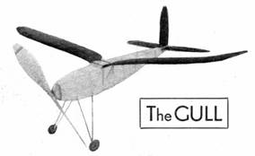
The GULL
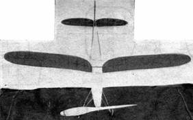
Bird Wing
There's a challenge to your
model‑building
skill, and worthwhile performance reward
in this graceful and efficient wing shape.
WHAT is the most efficient wing shape? Is it a taper wing, gull wing, straight wing, long, narrow wing, or short, stubby wing? Each modeler has a wing type he thinks is most efficient, and each is convinced his choice is the best. It takes only the slightest suggestion to start a group of builders arguing about wing shapes.
This month we present our favorite candidate for the honor of the most efficient wing shape. It's a gull‑shaped wing of aspect ratio 10 ‑ a value which falls between the extremely low value of 6 advocated by some and the higher values of 12 to 14 supported by others.
We picked a gull wing because it has certain advantages over the other types of wings. A wing which is tapered at the tips and at the center shows better efficiency than a straight wing which has uniform chord length throughout. A straight wing shows considerable drag and also a loss in lift both at the tips and at the center, where the wing joins the fuselage. The loss of lift at the tips results from the circulation of the air around the wing, which causes the air to spill out from the end. This breakdown in the air stream causes tutbulence and a resulting increase in drag and decrease in lift.
Where the wing joins the fuselage there is likewise a let‑down in the wing's efficiency. This results from interference between the air flowing past the fuselage and that moving over the wing. The result is that the section of the wing adjoining the fuselage shows marked increase in drag and decrease in lift.
There are two methods of improving the efficiency of this section. One is to fillet the wing where it joins the fuselage. These fillets make the transformation between the wing and the fuselage gradual and smooth out the airflow, thus reducing drag. But a more effective way of reducing the interference is to taper the wing where it joins the fuselage. Drag and lift both show desirable changes following a reduction in wing chord at the wing‑fuselage junction.
In contrast to the desirable aerodynamic characteristics, the gull‑shaped wing is undesirable from a construction viewpoint. The taper at the center makes it difficult to build in sufficient strength. If the wing is externally braced with struts, the problem is simplified, but in a cantilever wing it is a difficult problem. Likewise the shape of a gull wing doesn't lend itself to easy construction, the curved portions proving difficult. Fortunately these two construction problems are not as difficult in models as in real‑plane construction, so let's try the Gull.
Our model proved to be a good flier. It was not meant to be a contest ship, but one which can be flown repeatedly with little effort and trouble. Construction is fairly conventional and the instructions will emphasize the unusual steps in the procedure.
FUSELAGE
Making a full‑size drawing of the side is the first step. Draw the datum line and lay off 2-1/2" spaces along it. From the drawing find the depth of the fuselage at the various positions. The dimensions given are measured from the datum line to the outside edge.
The two fuselage halves can be assembled without the help of a full‑size drawing. Cut the cross braces to the length given in the top‑view plan and cement them in position. Pin the fuselage together while the cement is drying. Check to see that each half is bent equally. The upright pieces should be at right angles with the cross braces. Check this with a square or a triangle, for proper construction will insure an efficient, rugged job.
The rear tip is cut from a balsa block and cemented to the ends of the longerons. This block is tapered to a point to round out the fuselage shape.
Hard balsa 1/4 x 3/8 x 23" is used for the motor stick. The balsa nosing cemented to the front serves as a bearing for the propeller and as a means of securing the stick inside the fuselage. For this latter purpose the nosing should be grooved to fit. The rear stick support is a notched double piece of sheet balsa cemented inside the fuselage at the point labelled A‑A.
LANDING GEAR
Each half of the landing gear consists of a V made up of two bamboo struts, which are cemented and threaded to the fuselage. The actual strut lengths along with the landing‑gear tread are given in the drawing. Wheels of 1-3/4" diameter, preferably balsa, are used. A wire tail skid is bent to shape and inserted into the balsa block at the rear of the fuselage.
ELEVATOR AND RUDDER
Aerodynamically, a high‑aspect ratio elevator is desirable. This is especially true when a large‑diameter propeller is used. A long, narrow elevator will extend outside the turbulent slipstream of the propeller and will prove more effective than if it was entirely within the slipstream. In addition, a high‑aspect ratio elevator will show quicker recovery from stalls and bad flying attitudes. After a stall it picks up lift more quickly than the short stubby elevator and in this way makes recovery more positive. The aspect ratio of the Gull's elevator is about 6-1/2.
The theory that determines the effectiveness of the elevator also dictates the design of rudders. However, aspect ratios in both these surfaces are limited by structural difficulties. Getting sufficient strength into a long, narrow elevator is sometimes difficult if the weight is to be kept within a reasonable limit.
The elevator and rudder are shown full size in the drawing. The same shape of ribs is used in both and the outline of both surfaces is built up from sections of 1/8 x 3/16" balsa. Build up the complete outline, cutting it to shape from the drawing, and then cement it to the ends of the ribs. Finally, carve the outline into a triangular shape.
WING
The various ribs and the number of each required is given. Start the assembly with the five main ribs. Cement the upper and lower spars in position. From the front view of the wing, you'll notice that the tips and the center are curved. It is easier to force the wing into this shape than to try to bend the spars beforehand.
Merely twist the spars until they assume the correct shape and then secure the ends with thread and cement. Next add ribs A, B, C, and D.
The straight section of the leading edge is a piece of 1/8 x 1/8 x 8" balsa cemented to the notches in the front of each rib. The curved sections of the leading edge can be bent into shape between your linger tips. Simply grasp the wood tightly in your finger tips and force the wood into shape. Naturally this weakens the wood, but a liberal coating of cement will restore its strength.
The trailing edge is a triangular section cut from 1/8 x 3/8" flat balsa. The straight section can be made from an 8" length. The curved portions must be cut front 1/8" flat balsa, cemented together.
The two wing panels are made separately. For flying they are joined by a balsa center section. Rubber bands, joining the two wings, hold them rigidly in place.
PROPELLER
The size and shape, along with the method of carving, is given in the drawing. The free‑wheeling device is simple to make. Many model shops sell them four a few cents each. However, you can make an effieient substitute from a 7/8" length of brass tubing.
COVERING
Putting the covering on the wing is not easy. The best procedure is to cover the flat section with single sheets of tissue ‑ one on top and the other on the bottom. The curved portion at the tips and at the center must be covered with separate pieces. Make them small enough to include only the space between adjacent ribs. Spray tile covering with water and follow with a coat of dope. This procedure applies to the entire model.
FLYING
First check to make sure the tail surfaces are not warped. If they have twisted out of shape, pin them to a flat board and spray them with water. Allow them to dry in their pinned position. Thus will remove warps.
In the case of the wing, the tips ( beginning 8" from the ends) are washed out. That is, the leading edge is warped down.
For preliminary flying, the wing can be attached to the fuselage with rubber bands passing over the center section and around the fuselage. After the wing location has been determined, the center section should be rigidly cemented to the top of the fuselage.
The elevator is slipped through the rear of the fuselage and secured by a rubber band. Adjustments can be made by inserting slivers of balsa to raise or lower the leading edge.
The elevator incidence was about zero degrees. A convenient way to check the setting is to hold a yardstick alongside the fuselage with the edge parallel to the datum line. Extend the stick back underneath the elevator. For zero incidence, the leading and trailing edges should be equal distances from the edge of the stick.
Wing incidence should be approximately 1/4" at the center. As previously mentioned, the tips are washed out, which makes the incidence at the tips about zero degrees
When balanced for flying, the leading edge of the wing was about 8-1/2" back from the front tip of the fuselage.
SPECIFICATIONS
|
Span |
43-1/2" |
|
Wing area |
186 square inches |
|
Elevator area |
58 square inches |
|
Rudder area |
22 square inches |
|
Propeller pitch |
20 inches |
|
Wing incidence |
¼” (tips washed out to zero incidence) |
|
Elevator incidence |
zero degrees |
WEIGHTS
|
Wing and center section |
.70 ounces |
|
Stick, 14 strands 1/8 x 1/30" rubber, propeller |
1.50 ounces |
|
Elevator |
.25 ounces |
|
Fuselage, landing gear, rudder |
.75 ounces |
|
Total R. T. F. |
3.20 ounces |
MATERIAL
FUSELAGE
|
4 |
longerons 1/8 x 1/8 x 30" |
|
4 |
pieces 1/8 x 1/8 x 24" for bracing |
|
1 |
nose block 1‑1/8 x 7/8 x 2‑3/16" |
|
1 |
motor stick 1/4 x 3/8 x 23" |
|
1 |
piece 7/16 x 11/16 x 1‑1/4" for fuselage rear tip |
|
1 |
strip bamboo 7-1/2" length |
|
1 |
pair 1-3/4" diameter x 3/8" balsa wheel. |
|
1 foot |
#14 wire for tail skid. shaft, axles, rear book |
|
2 |
pieces 1/16 x 1 x 5" for balsa rear of fuselage |
|
1 |
piece 1/32 x 1‑1/4 x 5" for rear stick support |
WING
|
4 |
spars 1/8 x 1/8 x 20‑1/2" |
|
2 |
leading edges 1/8 x 1/8 x17‑3/4" |
|
2 |
trailing edges 1/8 x 3/8 x 8" |
|
|
1/16” sheet balsa for ribs |
|
|
1/8" flat balsa for trailing edge and tips |
|
1 |
strip of bamboo |
|
|
Several inches of light wire for wing hooks |
|
|
Center section 3/8 x 2‑3/8 x 2‑3/4" |
ELEVATOR and RUDDER
|
2 |
spars 3/32 x 3/32 x 18-1/2” |
|
2 |
spars 3/32 X 3/32 X 7-1/2" |
|
|
1/8 flat balsa for outline |
|
|
1/16 sheet for rib |
PROPELLER
|
1 |
block 1‑3/8 x 1‑5/8 x 15" |
|
|
Several cup washers and flat washers |
|
1 |
free‑wheeling device or 7/8" length of brass tubing |
MISCELLANEOUS
|
30 feet |
1/8" flat rubber |
|
4 |
large sheets of tissue |
|
2 |
ounces of cement |
|
2 |
ounces of banana oil. |
Scanned From December 1936
Air Trails
![]()
![]()
![]()
![]()
[ Home ] [ Previous Plan Pages ] [ Special
Things ] [ Earl Stahl Plans ]