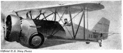
The real thing
The Plan Page
[ Home ] [ Previous Plan Pages ]
[ Special Things ] [ Earl Stahl Plans ]
Navy Hawk
Flying scale model of the
Curtiss Type III
plane that operates from carrier decks.
By
Alan D. Booton and Ralph Pickard
CURTISS BF2C‑1
The real thing
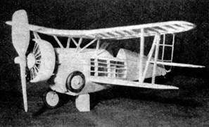
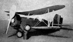
Our models,
demonstrating retractable landing gear.
A FAVORITE among Uncle Sam's war planes with model builders is the high‑powered, high‑performance single‑seat Curtiss biplane that has come to be known generally as the Type III Hawk. It is in daily active service with the navy in the capacity of light bomber and fighter aboard the aircraft carrier U.S.S. Ranger. Designated as the F11C‑3 and the BF2C‑1, it constitutes a powerful air weapon.
The Type III Hawk's speed reaches a top of 244 m.p.h. at 10,300 feet under the thrust of the Curtiss controllable‑pitch propeller turned by a 750 h.p. Wright Cyclone. Plans for a solid model of this plane appeared in AIR TRAILS for June, 1936. Part of the Hawk's high performance is due to flush retraction of the landing wheels, which is incorporated in our present flying model.
FUSELAGE
Make a sheet of balsa plywood with two1/32" sheets cemented cross grain, 6 x 7". After this is dry, cut two of each of the formers on drawing No. 4. Place the fuselage drawings Nos. 3 and 4 together on a smooth soft board and cover with waxed paper. Assemble the whole left framework right on the drawing. By doing this, the proper contour of the model is assured. When dry, remove from the board and build the right half frame to the completed left frame.
Before going further, make the wheels and the "wells" for the retracted wheels. The maximum diameter of the well blocks is indicated by the broken line circle on drawing No. 2. Hollow the blocks out so the wheels fit in flush with the back side, then cement 1/16" disks over the openings. To install them in the sides of the fuselage frame, they must be cut into three pieces and fitted in, removing the thickness of the formers from them. This is done to keep the weight down and to get them lined up better. Let the cement dry and then carve and sand away the surplus wood to the contour of the fuselage.
Cover the portions of the fuselage frame shown on drawings Nos. 1 and 2 with 1/64" sheet. Use plenty of pins to hold the sheet to the formers and butt the joints carefully to obtain a smooth surface. The tail‑wheel support should be covered with 1/64 " sheet, as shown.
Cement two dress snap halves to the front of former 1 in the positions shown on the drawings. Bend the rear hook from #12 music wire and install it on the rear of former 8 with a piece of 1/8" or 3/16" square.
MOTOR AND NOSE ASSEMBLY
Carve the nose form to the shape shown on drawing No. 4 and cement the built‑up 1/32" sheet crankcase to the front of it, then carve nine balsa cylinders and cement them evenly around the crankcase. Cement two 1/32” square bamboo push‑rods to each cylinder as they appear on a real motor. Carve the nose plug to the shape shown and cement a bushing in the shaft hole to prevent wear. The nose plug can be cemented to the crankcase if preferred.
Making the ring is a tedious job. Start with a 3 x 3 x 1‑1/16 tip," block and scribe the circles of the ring on it. Carve the inside carefully and then cement it onto the cylinders, where it may be finished up without danger of breakage. Add the exhaust stacks and scoops.
The remaining halves of the dress snaps should be cemented in shallow depressions in the back of the nose form to match those on former 1. Do this carefully in order to get a snug fit.
WING FRAMES
Only half of the wing‑frame drawings are shown. To get the opposite sides, place a sheet of white paper under the drawing and a sheet of carbon paper, face up, under the white paper. Trace over the wing‑frame drawings and the resulting tracings will be the opposite drawings required.
All wing ribs are accurately drawn. Cut two of each from 1/32" sheet balsa. In building the wing frames, the best procedure is to fasten every part in place before cementing, and to complete the panel before removing from the board. The top wing should be made as one panel, with 3/4" dihedral.
TAIL ASSEMBLY
Make the vertical tail with unfinished parts. Block the outline members up with scraps of 1/32" sheet to center the unfinished rib stock and spar. After removing from board, sand the ribs to the slight streamline shape, round the leading edge and taper the trailing edge.
Except for the sheet balsa tips, build the two stabilizer frames the same way. Since the individual parts of the tail surfaces are of minute size and the curves so slight, the light sanding of the assembled parts that have not been preformed or shaped is favored over the uncertain cut‑and‑dry method. This does not apply to endurance models.
RETRACTABLE LANDING GEAR
The three views of the landing gear make it hardly necessary to explain its action. Cut "A" shaped slots in the wells as shown and fit the wire parts to the model as in retracted position with the wheels on. After getting the desired action, cement the eyelets in which the swivel struts hinge and the short pieces of tubing in which the upper ends of the #14 wire struts hinge. To give the gear a better appearance, slide a length of 1/8" aluminum tube over the lower half of the long strut before making the bend at the top, or sheath the lower half with sheet aluminum after the cementing is done.
Make the small tail wheel and cement it on.
PROPELLER
Carve the propeller according to the blank on drawing No.1. Bend the hook of the propeller shaft, run the shaft through the nose plug, several washers, and the hole in the propeller. If you prefer, bend a winding loop on the front end of the shaft before cementing it in place on the propeller. Stretching the rubber and winding it will give surprisingly greater endurance.
COMPLETING THE MODEL
The best procedure is to carve a soft block to place between the fuselage and top wing to maintain the proper line‑up, then cement the cabane struts in place lightly to the wing; when dry, cut the wing loose from them.
Now cover all surfaces with the desired color of tissue and spray lightly with water. The tissue will sag badly when damp, but will become as tight as a drumhead when dry. Re‑attach the top wing on the struts with cement. Be sure to peel the tissue away from the spots to be cemented. Block the model up in neutral attitude and attach the lower wing panels to the fuselage. Block the tips up 3/4" and let dry, then fit the interplane struts.
Cement the tail surfaces in their positions. If an adjustable stabilizer is preferred, cement a spacer between the stabilizer halves and cement the halves to the fuselage at the rear only. Close the "A" slots in the landing‑gear wells by cementing balsa patterns behind them. Attach wheels, windshield and cockpit cover, gun‑sight, arresting hook, and fairings on the side of the fuselage.
If a flashier model is desired, light coats of colored model dope may be applied, with a small sacrifice of endurance.
MATERIALS
|
1 |
4 x 4 x 4" block medium balsa for motor ring, landing gear, etc. |
|
4 |
3/16 " sq. x 18" leading edges |
|
12 |
3/32" sq. x 18" spars, longerons |
|
4 |
1/8" sq. x 18" tail parts |
|
2 |
1/8 x 3/16 x 18" struts |
|
10 |
1/16" sq. x 18" stringers |
|
6 |
1/16 x 1/8 x 18" trailing edges |
|
3 |
1/64 X 2 X 18" covering |
|
8 |
1/32 x 2 x 18" ribs, plywood |
|
1 |
1/16 x 2 x 18" gussets, ribs |
|
2 |
sheets colored tissue |
|
1 oz. |
tube cement |
|
1 oz. |
banana liquid |
|
2 oz. |
(2 colors if preferred) dope |
|
6" |
alum. tube, |
|
9 |
bushings |
|
2 |
breast snaps |
|
6 |
washers, |
|
12" |
#12 music wire |
|
24" |
#14 music wire |
|
3" sq. |
model celluloid |
|
|
needle and thread for rigging |
|
3 loops or 72" |
1/8” flat rubber for motor. |
Scanned From November 1936
Air Trails
![]()
![]()
![]()
![]()
![]()
[ Home ] [ Previous Plan Pages ] [ Special
Things ] [ Earl Stahl Plans ]