FOLKERTS
SPECIAL
Racing Speed
"Toots" has contest‑winning zap as well as self‑lowering wheels, anti-torque aileron, and flaps!
by Alan D. Booton
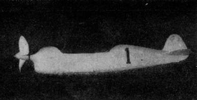
With gear up, ready to
go places fast.
|
|
|
DURING the past several years the trend in light racers has been toward cleaner and safer planes. The new Folkerts Special is an outstanding example in respect to its streamlining and ability to place high in speed events. The achievements of this little racer in the 1936 National Air Races are already well known in aviation circles.
The design of the Folkerts is excellent for a flying scale‑model racer. The large plane's features are included in the model to the best advantage.
The flaps are held up while winding the motor, at which time the right aileron rises from the rubber tension. After the motor is fully wound, the landing gear is pushed up into the wells, where it automatically latches, and the well hatches are closed, all by hand. Then as the propeller turns and the rubber unwinds, the aileron gradually resumes its normal position, and finally the flaps and landing gear snap down.
All of these features are incorporated in our 1-1/4 ounce model, and yet it has astounding speed under full control, made possible with the torque‑counteracting aileron. That sounds good, eh?
O. K. Let's start work.
The construction of the model conforms with that of the real plane. First make a 2 x 6" sheet of plywood of two layers of 1/32 " sheet cemented cross‑grained, from which to cut the fuselage formers. Now carve the cowl block from medium hard balsa. After obtaining the correct finished shape, apply several coats of dope to protect the finish.
The two side 1/16” ‑ square longerons are cemented in the step in the cowl block and are left to dry parallel to each other. This is important, because the formers are assembled on the two side longerons.
After cutting the formers, cement them to the longerons. The bottom of the #3 section is fitted with a former to take the landing‑gear hinges (D). Cement the top and bottom longerons into the slots and check carefully to see that the frame remains lined up as the cement sets.
The wing panels are simple to make. Cement two layers of 1/64" sheet balsa together cross‑grained to form a 6x12" sheet of plywood. Cut the oversize wing panels from this and make certain you have two pairs, and that the exposed grain will run from the roots to the tips.
Pin the two bottom panels (a right and a left) to a board and assemble the ribs by cementing directly to the panels. Remember that both flaps operate. Only the bottom panel is cut for this purpose, in order to leave the top panel intact. The flap ribs and spars are independent of any other assembly and are kept so by using small pieces of waxed paper where a stick‑up seems likely. Only the right aileron is controlled and it, also, is independent of the wing.
The procedure was to assemble the wing panels to completion and then cut the plywood where necessary by holding the wings before a strong light to see the spar divisions.
After removing the flaps and aileron, cement the flaps back to the bottom surfaces of the wings with jap‑tissue hinges. The aileron hinge goes on top.
The stub spars should be cemented carefully and firmly into the wings before the top covers are put on. They were purposely included to aid in getting the wings lined up on the fuselage.
Now mount the wings on the fuselage frame with 1/2 " dihedral angle.
AUTOMATIC MECHANISM
Study the parts and their purposes as shown in the various drawings. They may seem complicated at first, but careful examination will reveal that they are not difficult to construct. The "rear hook" mounting, illustrated in drawing 3, is the heart of the whole thing. Instead of having a rigid hook, a crank-like wire part, moving in an aluminum tube bearing, rises as the rubber is wound and pulls the control bar back about 1/4 ". The control bar connects with the aileron crank, giving constant control, at X on drawing 1. Then at Y the doubled reverse bend in the control bar locks the flap control wire, if it is held up while winding, and when the motor runs down, the bend slips past the flap wire Z and releases it, letting the flaps down.
On toward the front, the landing‑gear release latch is shown, in four different views provided to make that part clear. The latch is bent like a door‑lock latch on the end of a crank. At the top of the tube, a plain crank is bent at an angle to derive the force from the rear-hook coupling, which is bent with a long eyelet to slide on the latch crank. A small spring holds the latch in engaging position when the motor is wound so the landing gear can be retracted, and yet the long eyelet is adjusted so it forces the latch off when the motor runs down.
The landing gear struts are in tripod shape as on the large plane. The struts C extend to the center of the fuselage and have bends made as illustrated, which make an equalizer. The "equalizer" holds the two landing‑gear halves in corresponding positions at all times and also allows for the cross center movement of the extensions. That is why the long loop is made. The landing gear wires had to be soldered together in spite of the effort to evade this modelbuilder's hate. A spring of suitable strength holds the landing gear in the down position, eliminating the use of down lock and gaining a darn good shock absorber.
All in all, the three operations depend on the control bar being drawn back as the motor is wound and then moving forward again as the motor unwinds. The latches should be arranged so they release just as the motor completes unwinding.
COMPLETING THE MODEL
Split the top wing cover with an undercutting slice along the line of the aileron control. Force the control wire down on the ribs to make depressions and then cement the cover back together. It is best to leave the aileron off until the control is in. The aileron should be neutral with the motor unwound. Assemble the control parts and test them thoroughly before proceeding with the remainder.
Cover the top of the fuselage between formers 3 and 4 and make the cockpit covers of 1/32" sheet with celluloid openings. Make the windshield of two celluloid patterns and set it aside to attach when the model has been doped.
The tail surfaces are three‑ply wood sanded to a streamline shape. The outside ply sheets are parallel 1/64 " sheets over cross‑grained 1/32" sheet. The two opposing plies tend to prevent warping, if dried properly. Cement the tail surfaces on.
Add bamboo stringers along the fuselage. The stations for these are not shown on the drawings for clearness and because you would prefer to use your own number. Eleven tapered stringers were used above and below the side longerons on the original model.
Cover the model with yellow tissue. After the tissue has been dampened and dried to draw out wrinkles, dope the wings red and the fuselage and tail yellow, using the numerals and scheme shown on the model and in the Gallery photo on page 31. Now attach the windshield.
FLYING THE MODEL
The speed propeller designed especially for this model gives the best results. Leave the blades thick at the spinner and taper the thickness to the tips. Maintain the helical pitch, by all means. The first motor of four loops of 1/8" flat, brown lubricated rubber should be installed before covering. After that, a small hole must be cut in the rear of the fuselage to reach the "S" hook.
While testing the model, bind the landing gear and flaps in up position with rubber bands. Try to test in tall grass until you are confident of good adjustment, then use the controls you have sweated so much over and get a real thrill from seeing the things happen "up there."