| Build This Swell "Thermal Chaser" When Ace gas-job designer Gil Shurman tacked his drawing paper onto the drafting board he had a whole slew of great ideas. And when a petrol builder turns to rubber craft -- almost anything can happen! This time, though the old stick-to-your-own-game idea didn't hold, for this "Thermal Chaser" proved to be a top-notch sleek-sailer! By Gilbert Shurman Author of "‘Mike' Gas Job," "'Rambler' Gasoliner," etc.
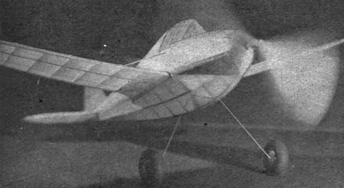
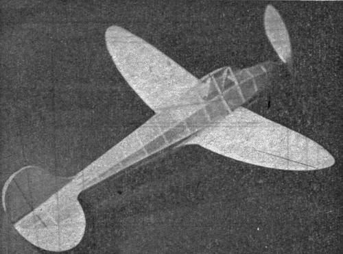
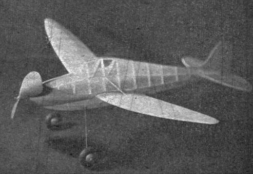
ATER the Nationals have passed into history every summer, lucky winners usually loaf on their laurels -- if they've won any -- while less fortunate ones resign themselves to the lull of mid-summer activities -- until it's time to again prepare for the Grand Brawl. So at the request of ol’ Doc F.A., the author wracked his gray matter to design a ship that would pack the punch of the proverbial "shot in the arm." And the "Thermal Chaser" is the one inducement to bid that lull a bye-bye! This little ship consistently turns in top-notch ROG flights with only 400 hand winds. And hand launched hops have been clocked for times that would make any fan happy. Okay, that's enough of that. Here we go with all the dope -- FUSELAGE AND WING THE "Thermal Chaser" has a 22" span, elliptical wings and stabilizer, and a diamond-shaped fuselage. What's more, she's even simple enough for a beginner to make. Before starting to build the model, read the instructions carefully to be sure all construction details are thoroughly understood. The fuselage drawings are shown half size. This will necessitate their enlargement to full size. Only the outline of the top view is necessary, for in construction the 1/8" square longerons are pinned to the top and the bottom half of the fuselage built first. When completed, it is removed from the plan and then the top half is built onto the bottom segment. In enlarging the plans, a greater degree of accuracy may be attained by using a pair of dividers when taking measurements from the drawings. And during the construction of the fuselage, it is advisable to use several temporary 1/8" square braces to hold the main longerons apart and in their correct shape. The main bottom stringer, marked "S-3," is cut from 1/8" sheet balsa. The correct shape of this part may be transferred onto the balsa by placing the plans over the wood and pricking through the drawing with a pin. After "S-3" has been cut out, it is glued to the rear of the main longerons and propped up in the front 7/8" from the table by a temporary piece of 1/8" square balsa. Now all the 1/16" braces are cemented in their correct positions. When dry, remove the lower half of the fuselage from the plan and attach "S-2," propping the front up 2" from the main longeron. Add cross braces of 1/16" square balsa and then attach "S-1," using as many pins and temporary braces as necessary. Before the nose of the fuselage can be finished, it is necessary to add the 1/16" square auxiliary stringers. These are glued directly to the braces and fair neatly into the rear of the fuselage. At the nose, the auxiliary stringers are pulled together and cemented to the front body braces; then the braces from the front of the fuselage to the cabin can be glued in place. Cap strips of 1/32" by 1/4" are attached to the top and bottom stringers and 1/32" by 3/16" caps are likewise added along each main longeron. A piece of 1/32" sheet balsa is cemented to the nose. After it has hardened, trim to the shape of the fuselage nose. When attaching the landing gear, which is bent from .034 wire, be sure to use plenty of cement. Arrange the braces and chocks as shown on Plate 2 of our drawings. The celluloid windows are added after the fuselage is covered. No difficulty should be encountered in the construction of the wings and tail, since they may be built directly on the plans. Only half the wing is shown, but duplicating it is a simple procedure. The outlines of the tail and the trailing edge of the wing may be best obtained by the pin-pricking method. COVERING AND ASSEMBLY IT WOULD be well at this point to review the correct procedure for covering and doping the surfaces of your model. The author feels, because of the "Thermal Chaser's" elliptical wing tips and tail and the unusual shape of the fuselage, one may assume a different technique is required in applying the tissue. This does not hold true, however, for if the correct procedure is followed, even a beginner will be able to turn out a neat job. First off, when the skeleton parts are ready for covering, a light sanding on all edges and surfaces should be made to prevent bumps or irregularities from showing through the tissue. It is advisable to cover the stabilizer first, as that part should be attached to the fuselage as soon as it is completed. Apply a coat of adhesive dope to the wooden frame and lay upon it an oversized sheet of paper, its grain running lengthwise. Fasten the tissue to the center root rib. Now, by carefully pulling all around, the wrinkles will straighten out and then the paper may be doped to the leading edge. Thus the tissue is fastened to the wing outline which allows for shrinkage all around. The lower part is covered in the same manner. After trimming off the excess material, the covered part should be given a light water spray with an atomizer. At least fifteen minutes should be allowed for complete shrinkage. And when all moisture has evaporated, apply one coat of dope to the surfaces. If necessary, brush on a second coat to eliminate remaining wrinkles. The rest of the model is covered in the same manner. ASSEMBLY AND DECORATING WHEN putting the various parts of the model together, follow the instructions carefully. First, glue the stabilizer to its proper place in the fuselage. The correct setting for the stab is flush with the top of the main longerons. Each wing panel is now cemented to the main longeron. Take care to provide at least a 3/16" incidence angle. Since the longeron is curved, the root rib of the wing will, only contact the longeron from the leading edge to the spar. To strengthen this joint, and fill in the apace between the wing and body, a 1/32" fillet is cemented between the trailing edge of the wing and to the fuselage. Next, 1/64" sheet balsa is cemented to the wing and the fuselage tissue. This will have to be cut to the curve of the body by the trial and error method. Both the bottom and the top of the wing are covered by this 1/64" sheet fillet. After the wing is covered, a 1/32" by 1/16" bamboo strut is glued in its proper place as shown on the plans. The dimensions for an 8"propeller will be found on the drawings. It is best to first carve the undercambered sides and afterwards the front face of the blades. The outlines should be smooth and identical on both blades. Sand the prop with fairly coarse paper at first and complete with fine paper. The prop freewheeler is of the spiral type. However, any light, smooth working freewheeler may be substituted. Carve the nose plug from a block of scrap balsa. A tight fit in the nose of the fuselage is desirable as this will prevent the plug from falling out when the rubber unwinds. To provide for less friction and greater accuracy in the thrust line, two eyelets are forced through the shaft hole -- one in front, the other in the rear. A ball bearing washer is recommended, but two or three flat washers between the prop and nose plug are sufficient to prevent loss of power. Incidentally, these washers should be kept well oiled. FLYING THE MODEL THE "T.C." FLIES on eight strands of 1/8" flat rubber. However, should your job act loggy, use ten strands. To test fly the model, don't attempt to glide it. This may sound strange to you, but experience has taught me that nothing important can be gained from hand launching such a small, light model as this one. Select a calm day and a broad field for testing. Allow the model to taxi about, gradually increasing the number of winds until it attempts a takeoff. Note carefully any irregular tendencies and correct them immediately by shifting the thrust line in the right direction. This can best be done by inserting strips of wood between the nose plug and fuselage. Never, under any circumstances, change the angles -- assuming they are correct -- between the wing and stabilizer. All adjustments should be carried out by changing thrust or by using a bit of clay for weight. Better flights may be obtained by providing a slight amount of right thrust, and right rudder. This will allow the model to circle to the right under power and also in the glide.
Scanned From October 1940
|