|
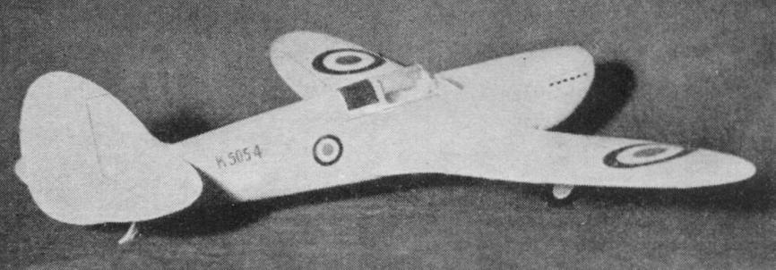
SUPERMARINE SPITFIRE I by Alan D. Booton and Ralph Pickard
Fastest War Plane That's the reputation of Britain's new job, presented in
a fine flying
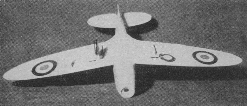
A bottom view showing the automatic landing gear extended and retracted. It is rumored that Britain's Supermarine Spitefire I is the speediest single-seat fighter in the world, but since all performance records are held secret, no certain comparison can be made. It is known, however, that the plane is very maneuverable at high speeds and has proved itself so well that an appreciable number have peen ordered. It is a product of the Supermarine Aviation Works, a division of Vickers, and it is powered with a Rolls-Royce Merlin engine. Photos of the plane appeared in this magazine for September and October, 1936. Prior to this issue, AIR T RAILS has presented several all-balsa flying-scale models that were miniatures of all-metal or plywood planes. We'd like to sum up the advantages of this type. It is next to impossible to duplicate the appearance of rounded metal parts with tissue covering, and to overcome this difficulty, suitable model structures were covered with a special 1/64" sheet balsa now available. The finished all-balsa models were lighter (even with automatic controls), better balanced, and were more easily repaired than the ordinary multistringer tissue-covered types. Considering the many stringers around the moment arm, the number of coats of dope to finish the tissue, and the heavy tail-surface members that have to be balanced with weight in the nose of the scale-appearing tissue-covered models, it is no wonder that they are slightly heavier. The Spitfire model presented this month is one of our typical all-balsa jobs, including optional controls. Read the instructions and study the drawings carefully for the all-balsa construction procedure, and start by making a 4 x 6" plywood sheet of two layers of 1/32" balsa for the formers to be cut from. FUSELAGE Carve the cowl block, using the top and side views and then the section templates. If you favor building the first half of the fuselage frame cm the side-view drawing, split and hollow the cowl block, and then proceed in the usual manner. If you prefer the method by which the two side longerons are cemented to the cowl block and the formers then arranged on them, do not split the cowl block; just hollow it according to the drawings. Be sure the fuselage lines up if the latter method is used. Make the rear-hook device, sew and cement it to former #9. Attach wing panels before continuing. WING AND TAIL Wing-panel and tail-surface frames are covered with single layers of balsa sheet, instead of the usual plywood, because of abundant frame members. The sheet cover can be replaced by tissue, by the addition of trailing edges, but the balance and appearance will be lost. Cut four 1/64" sheet wing-panel patterns according to the broken oversize line. The grain should run from ribs 1 to the tips. Cut the ribs from 1/16" sheet and save the remnants from the bottoms to hold the bottom covers up to the respective ribs as the frames are assembled on them. Except for the aileron on the right wing only, the wing frames are interlocking and need no sketching of reference lines on the lower covers; just use the trailing edges as a limit. Cut a pair of stub spars as indicated on drawing #4, when cutting the main spars. Assemble all frame parts on the bottom covers and pin them securely to the board; block the bottom covers up against the rips with the rib remnants; pin the covers to the board and then remove the frame parts, leaving the cover patterns as they are. One frame at a time, content the ribs to the spar, flow a coat of cement along the bottoms of the ribs and spars, and replace on the bottom cover with plenty of pins. A 1/8" sheet tapered strip to fit under the trailing edge to the tip of each pattern will insure a straight edge without "fussing" when the top cover pattern is laid on. After the cement has set securely, "toenail" rib 1 and the tip to the board and remove all other pins. Flow a coat of cement all around the edges and across the tops of all ribs. Do this quickly (a tube of cement is the solution for speedy application) and then pin the top covers on, trailing edge to trailing edge first, leading edges next, and then the tips. This is when the 1/8" tapered strip comes in handy; it permits the tip edges to be fastened together uniformly by pinning through several cut-to-shape scraps at the tip edges to prevent buckling. After the cement is thoroughly dry, remove the panels from the board and sand the rough or square edges to the final shape. Hold the right wing panel to the light and cut the aileron out. The tail surfaces are built in the same manner as the wing panels, but are easier to do. Note that oversize rudder and elevators are arranged so that scale surfaces may be substituted. Soft iron wire may be used for hinges, but less trouble will be encountered if the controls are spot-cemented on. Cement the wing panels to the fuselage frame by the spars. Be sure to have 1/2" dihedral angle or more. The wheel wells and strut ways may now be cut out. Additional space, 1/2 " wide, between ribs 1 and 2 directly behind the stub spars must be cut out to notch for the latch control and the landing-gear axes and then replaced later. CONTROL MECHANISM The idea is the same as in the Folkerts Special and Time Flies (see AIR TRAILS, January and February) except for the adaptation to this particular model. This one is very simple and should not be overlooked. The principle is like this: suppose the motor is unwinding; the diminishing tension of the motor lets the spring at the rear pull the control bar forward. The control bar moves the cranks on the aileron control and the latch bar forward, easing the aileron down gradually as the torque diminishes and releasing the landing gear, which has been set manually. Make the parts of the size wire indicated on the drawings. The wire guides on formers 7 and 8 prevent the control bar from buckling. Cut 1/16" slots through the ribs to the top cover to install the latch bar and cement balsa back in the slots. The landing gear hinges or axes require 1/4" slots. Be sure to include the tension springs when cementing the landing gear in place. FUSELAGE COVERING Make certain the control mechanism works freely. Cement the tail surfaces on and cover the fuselage frame as follows: the top and sides from the cowl back to former 6, the sides between 6 and 7, the top half between 7 and 9, the bottom half between 7 and 9, the wing fillets, and then the bottom "patterns." If the insides of the back cover patterns and the outsides of the fillet patterns are coated with cement and dried, they can be shaped with the fingertips, the fillets especially. Pins and rubber bands are a great aid in covering with sheet balsa. PROPELLERS A 1/8" sheet retainer washer cemented in the nose receives the nose plug. A scale propeller may be carved if desired. The flying propeller is carved as a speed type. Leave the blades thick at the spinner and taper to at least 1/16" at the tips. Sand the prop between coats of dope until it has a high gloss. Attach the prop to the nose plug in the usual manner, but bend a winding loop at the front. COMPLETING Attach tail skid, radiators, wheel covers and then spray or brush all over with thinned clear lacquer. Sand carefully with very fine sandpaper, and then coat the whole model with aluminum lacquer (one-half thinner, one-half clear lacquer with fine aluminum powder added). Do not use dopes, for they will draw the wood out of shape. Now place the cockpit cover patterns, insignia, exhaust stacks, numerals, tail surface threads, and paint the tires black. FLYING The original model weighs exactly 1.5 ounces, ready to fly. Use three loops of 1/8" flat lubricated rubber, equipped with an S hook. Cut a 1/2 x 3/4" door forward of former 9 in the side of fuselage below the middle longeron. Hold the model upright and drop the rear of the motor through the fuselage and engage the S hook to the rear-hook device, through the door. Replace the door, with a tissue hinge. Make all glide and flight test; in tall grass. If the automatic aileron raises too high, cement a wire stop to the wing so it can be bent to adjust the height of the aileron. Happy landings! MATERIALS
Scanned From March, 1937
|