|
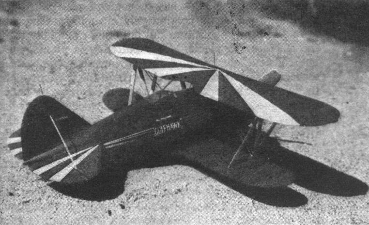
GULFHAWK By Alan D. Booton A carefully designed flying model for discriminate builders, a model faithful to its prototype in every detail and built to stand abuse The 1,000 h. p. GRUMMAN
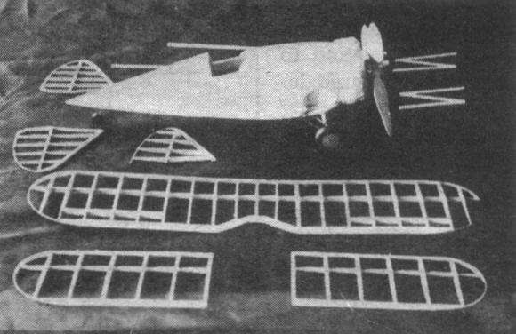
THE air-minded youngsters of to-day invariably visualize a trim, speedy plane when associated with Major Al Williams, who has a most enviable record with fast ships. The latest Williams Gulfhawk is the Grumman G22. built especially for him. This amazing little ship is powered with a Wright, single-row Cyclone of 1,000 h.p. and has a top speed of 290 m.p.h. The G22 differs only slightly from the navy fighter. The beautiful color scheme of orange, striped with blue and white, stands out under almost any light condition and can easily be one of the handsomest models to grace your collection. The model has been designed carefully to preserve the sleek lines and features. It is extremely fast and stable with the proper adjustments made. FUSELAGE Cement the two 1-1/2 x 3 x 18" soft blocks together, with several drops near the center so they may be separated later. Trace the side view of the fuselage, less cowl, onto one side of the block so that the bottom curve is at the edge. The block will not be quite high enough at the top, so saw along the bottom curve and cement the remaining piece to the top. Then complete the side-view blank. (A larger block combination may, be used if desired.) If the top and side views are traced onto thin cardboard and cut out for templates, marking the lines on the soft wood will be made easier. Draw the top view onto the top face, using the joint between the blocks as a center line and saw away the surplus. Now sand the blank to smooth the Irregularities of the saw cuts. Start carving at point C, otherwise the blank is likely to be spoiled. Cut templates of cardboard of A, B, and C to aid in the final shaping. After carving closely as necessary, sand the remainder of the wood away. It is important now to dope and sand the fuselage. The next step is to hollow the wheel depressions, or landing-gear wells. A cardboard template of the outline will insure getting both sides alike. Carve the wheel wells 1/4" deep and the strut wells 3/16" deeper. Sand and dope until glossy. Split the blocks apart and hollow the halves. A spoon - shaped tool (page 56, October AIR TRAILS) is the best for this purpose, or a thin double-edged razor blade, broken in half lengthwise -- the ends of one half bent back and inserted 5/8" apart in an improvised handle -- will do. Carve to paper thinness back of the rear hook position and gradually increase the thickness to 1/8" at the front. Leave plenty of thickness around the wheel wells. A 1/16" sheet bulkhead should be fitted in halves at point C. Insert the snakelike rear hook with plenty of cement just at the time the two halves of the fuselage are being cemented back together. COWL From the remaining square end of the fuselage block, saw off the necessary length for the cowl. Carve and polish and then hollow it. The motor block is merely a 1/4 x 2" disk with the cylinder detail done in base-relief. The 9 cylinders are laid out, carved, sanded, doped and lacquered black. The fin impressions are then made by closely spaced knife cuts. The push rods are broom straws, ignition ring 1/16" aluminum tube and the wires thread. After all detail has been added, cement the motor into the cowl. A removable nose plug shaped like the crankcase is then added. LANDING GEAR A serviceable landing gear, closely resembling scale, can be made from aluminum tube pinned together, or a less pretentious one of music wire will do. The one on the original model is automatically released, but is too complicated for the average builder to tackle without cussing. WINGS Build the wing frames on the drawings laid on a flat surface. Before removing the top frame, crack the frames at the second 1/16" ribs, raise the tips 1/2 " with blocks and cement the cracked members. Carve a pair of fillet blocks with which to attach the lower wings to the fuselage. TAIL SURFACES Assemble the tail surfaces with plain unshaped stock as designated on each member. Then sand to the required streamline shape. PROPELLERS Both scale- and flying- propeller designs are included on the drawing. Cement three blocks together, with the center lines 120 degrees apart. Then blank and carve in the usual manner. FINISHING Cover the wing and tail frames with orange tissue anal attach them to the fuselage. Attach the top wing first by using a 1/8" sheet block shaped like the space between the fuselage and the center section. Pin the block to the fuselage and then the wing to the block. In this manner the center struts can be accurately fitted so the wing will have zero incidence. With the top wing in place, it is an easy ,job to fit the N struts and the bamboo rigging wires. Spray the tissue lightly with water and when dry, apply thin model dope. FLYING THE MODEL Power the model with 3 loops of 1/8" flat lubricated rubber. Make the first flight tests in tall grass until a fully wound flight has been made. Stretching and winding the motor will give improved endurance. LIST OF MATERIALS Blocks
Strips
Miscellaneous
Scanned From December 1937
|