|
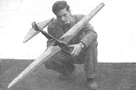
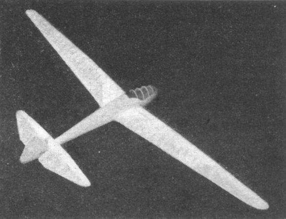
WIND MASTER By Roger Hammer In collaboration with Gordon .S. Light Complete instructions for building and flying a Ross-Stephens Soarer
THE MODEL of this famous sailplane turns in the same championship performance as its big brother. It has a smooth, steady glide that takes advantage of every helpful current. The original model weighed 5 ounces and turned in good flights. This model was overweight, since extra care was taken to work out every detail of the large ship, with special attention to an extra - fine finish. The beautiful appearance of the model was worth the handicap of increased weight. It was not hard to realize why gliding and soaring is such a thrilling sport. Watching the effortless flight of this graceful soarer has made us pretty enthusiastic. If you are interested primarily in performance, you will do well to reduce the weight of the model to about 3 ounces. A model of this weight should fly out of sight no time at all. The performance of the heavier 5 ounce model proved this to be true. CONSTRUCTION The original model was built to 1/10 the size of the full-sized ship. This scale is convenient to follow and produces a model of a size most convenient for model flying. FUSELAGE The fuselage is cut from a solid balsa block 2-1/4 x 4-1/8 x 21-5/8". This block dose not have to be a single piece of balsa but can be made up of several pieces of balsa cemented together. Templates are not necessary when shaping the cross section of the fuselage. Mark the shape of the side of the fuselage on the balsa block. Cut away the excess balsa and shape the block to the side view in the drawing. Next mark off the shape of the top of the fuselage on the balsa block. After cutting the top to shape, you'll have the desired fuselage shape except for the square corners. Cut away these corners to form the oval cross section of the fuselage. The cross-section shape of the fuselage which is shown in the front view of the drawing extends throughout the length of the fuselage. Take care to make your fuselage with a smooth, even-curved shape, keeping the depth and width of the fuselage indicated at the various stations along the length. Hollow out the inside of the fuselage from station G backward to the tail. The fuselage walls should be thin enough to permit seeing light through them when held over an electric bulb. From station G forward the fuselage is hollowed out to a wall thickness of 1/4". There is no advantage in reducing the thickness of the walls in the forward part of the fuselage since the weight is necessary to balance the model. The top, forward part of the fuselage is built to duplicate the cockpit of the large ship. The balsa is cut away and bamboo rings are substituted for the curved portion of the fuselage. These, in turn, are covered with celluloid to give the effect of the cockpit cover. ELEVATOR AND RUDDER It was found necessary to practically double the elevator area of the model over that of the scaled-down elevator. This change in elevator area is the only necessary variation in scale. It does detract from the scale appearance of the model to some extent. But in the eyes of the experienced modeler it will seem attractive, since it means better performance. Elevator construction is conventional throughout. The 1/32" sheet balsa streamline ribs are cemented to the 1/8 x 1/4" balsa spar. A1/8 x 1/8" leading edge is inserted in the notches in the front of each rib. The trailing edge is triangular-shaped and butt-joined to the rear tips of the ribs. The top and bottom of the front portion of the elevator is covered with 1/32" sheet balsa as far back as the spar. The elevator is built in one piece. Cut away the rear of the fuselage when attaching the elevator. Any unsightly holes which you might carelessly cut in the fuselage when mounting the elevator are easily repaired by patching with scraps of balsa and cement with a follow-up treatment of sandpaper. The rudder is built in one piece and cemented to the rear of the fuselage. A movable rudder serves no particular purpose other than making the model a more accurate scale job. All necessary adjustments call be conveniently made by warping the rudder. It shouldn't be necessary to make much adjustment. The main spar of the rudder is 1/8 x 1/4" tapered to 1/8 x 1/8" at the tip. The ribs are streamlined with a maximum thickness of 5/16" at the fuselage, changing to 3/16" at the tip. 1/32" sheet-balsa covering is used on the forward part of the rudder. The curved outline of the rudder is Cut from 1/8" sheet balsa. WING The type of wing construction was first introduced to modeling by Roger Hammer of New York City. He has used it successfully on many models and did an outstanding job with this model. The sketch will show clearly the fundamentals of wing construction. This method is the ideal way to make an accurately tapered without the trouble, accompanying the usual way of tapered-wing construction, that necessitates cutting each rib to a different shape. The top and bottom curved pieces which make up the shape of the wing are all cut from the same template. These pieces are cemented to the top and bottom of the spar. This spar is carefully tapered from 1/8 x 11/16" at the center to 1/8 x 1/4" at the tip. The length is 27-1/2". The accuracy of the taper will have an important effect on the shape of the finished wing. The rear tips of the rib pieces are cut to meet the required length at the various positions. Construction is easily carried out by working over a full-size layout. The top and bottom rib pieces are cut from 1/16" sheet balsa in the same way as in the construction of indoor models. ATTACHING THE WINGS TO THE FUSELAGE The center section is built into the fuselage. The center-section spars extend through the fuselage. The ribs are solid, cut from 1/16" sheet balsa. The center section is completely covered with 1/32" sheet balsa. The ends of the spars -- 2 inches beyond the end rib -- of each half of the wing fit into balsa boxes which are cemented to the center section. This box spar is made by waxing the end of the main spar and building the box directly on it. The wax will prevent the box spar from "sticking" to the main spar. This method insures a perfect fit. 1/16" sheet balsa is used in the box spar with a double covering of tissue. The box spar is cemented to the finished center section. An auxiliary fastening is used at the rear of the wing to prevent twisting. A piece of .040 wire is cemented to the inside of the trailing edge of the wing. This wire fits into a piece of aluminum tubing which is cemented inside the center section. FINISHING Wing and tail fillets are made with balsa dust mixed with dope or cement and followed with about 5 coats of wood filler. The fuselage is given several coats of wood filler before painting. Black paint was used on the fuselage with a rubdown of wet or dry carborundum paper 360 and 400A. The wings and tail are covered with yellow tissue, doped with water and model dope. No controls on this model were movable. The outlines of the ailerons has been shown if you want to paint them in. The spoilers were likewise ignored since they don't have much use in model work. Scanned From December 1937
|