|
Building the Boeing XP-940 by Model Editor and Designer for POPULAR AVIATION
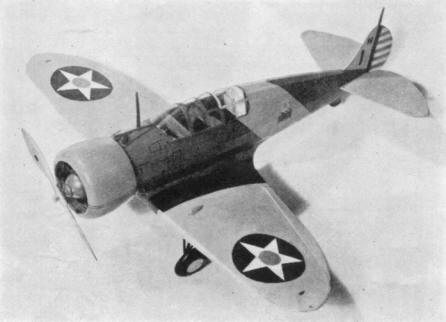
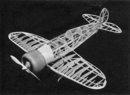
THE Boeing XP-940 was developed for the U. S. Army Air Corps as a single seated pursuit fighter. All data in regard to speed and so forth is kept a secret by the Army Air Corps. You will find the model to be a very speedy flyer. Then, if a great deal of time is spent in applying the details and so forth to the model you will be repaid with a very attractive display model. COLOR SCHEME Entire fuselage army blue with necessary striping. Wing and tail surfaces, army yellow details in black and silver, other color notes are indicated on the plan. CONSTRUCTION OF FUSELAGE It is necessary to place a sheet of ordinary wax paper over the plan to prevent cement from sticking to it. In building the fuselage, construct one side at a time. The longerons, vertical and diagonal braces, etc., are held in place until securely cemented, by inserting straight pins on either side of strips. After the two fuselage sides are completed, they are pinned to top view of the plan in such a manner that the top longerons face down and the sides are at right angles with the table. The cross-members are now cemented in place, forming a rectangular fuselage. Cut formers from 1/16 inch sheet balsa and cement in their respective positions as shown on plan. Balsa nose plate is built up from 1/8 inch sheet balsa. Stiff paper is required between nose plate and formers. The cylinders are carved and sanded from balsa blocks. When nine cylinders have been formed, wind heavy thread around them to represent fins. Make crankcase from two pieces of balsa. Rocker arm housings, push rods and other small details of motor are made of balsa. CONSTRUCTION OF WINGS Cut all ribs from 1/16 inch balsa. Pin the spar in position on the plan. Now cement ribs in their proper locations. The leading and trailing edges are cut and sanded to shape and cemented to the ribs. The panels carry movable ailerons which are a great help in controlling the flights. Make wing tips from 1/16 inch thick balsa. We highly approve of this type of wing tip, because it is much easier to construct and neater in appearance. CONSTRUCTION OF ELEVATOR A\D RUDDER These are built from 1/16 inch square and flat balsa, and are constructed on the plan. Their construction is very simple: therefore no difficulty should be encountered here. CONSTRUCTION OF LANDING GEAR Study plan carefully to clearly understand the construction of landing gear. The method in which the landing gear struts are attached to the wings is plainly described. COVERING THE MODEL Apply tissue to the various framework members, using a light grade model airplane dope to fasten it to the outer edges. Scanned From May 1937
|