|
The RYAN S-C
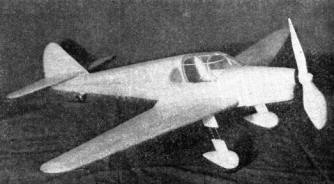
by Alan D. BootonReal performance with a flying scale model -- a lightweight, large size model emphasizing stability and duration
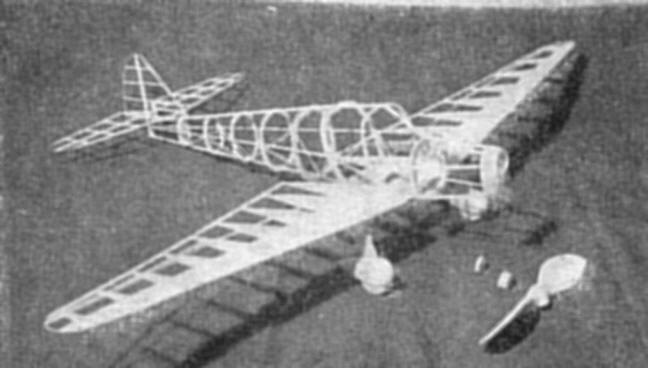
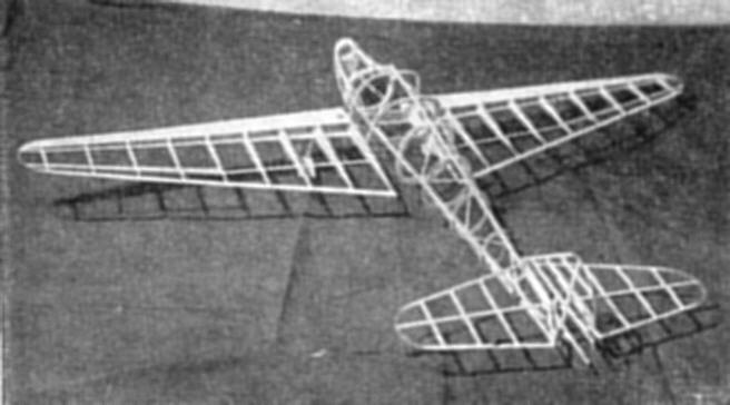
PRODUCTION has just been started by the Ryan Aeronautical Company on the two models of the new S-C three-place sport plane. The only difference in these two models is the choice of a Warner or a Menasco engine. The performance of the ship is approximately the same with either engine, top speed being 150 m.p.h. and landing speed 45. The Ryan Company is a pioneer of metal construction in planes, and in the model of the Menasco powered S-C it will be noted that the metal fuselage is simulated, together with other external features. The model is larger than usual and of simple construction, and due to its size, makes longer flights than could be expected otherwise. FUSELAGE Prepare a 6 x 8" sheet of 1/16" balsa plywood by cementing cross-grain 1/32" sheets. Keep this weighed down several hours to dry, then cut out the formers in pairs, except DT, which can be cut from 1/16" sheet. Pin the top and bottom longerons to the drawing and cement the formers to their respective stations. The drawing shows a continuation of the top longeron to aid in assembly. This is cut away just before covering the fuselage forward of F. Bend a strip of 3/32" sq. so that it will lay in the former slots without forcing, then cement it in place. Cement 1/16" sq. diagonals between the formers from the bottom longeron to the middle longeron. After this is dry, remove from the drawing and build the other side directly to it in the order the first half was made. Include the rear hangar as F is cemented on. Since there is no bulge in the fuselage to the rear of former F, the sheet covering can be wrapped around the frame like a cone. Cut 1/32" sheets diagonally to form an oversize pattern similar to the miniature pattern on sheet 2, in a dry state at first, then when the setup is satisfactory, cement the parts together. When dry, cement the top longeron to the center of pattern. In other words, invert the frame and cement it to the blank. When dry, wrap the cover around the frame and trim away the excess sheet, then cement members that will touch the sheet, and with rubber bands bind the cover to the frame. Cover the frame forward of F with narrow sheets. Cement plain #1 ribs (1/16") to the stubs of E and F in the position shown by the broken lines of the rib on sheet 2. Cement the fillet sheets on. These must be made by cut-and-try with pieces of paper, but the final appearance will be noted by reviewing the photos. Cut away the temporary top longeron, complete the top of the fuselage front of the cabin and then frame the cabin with bamboo. The Menasco cowling is made the way the fuselage was. First carve B and slice it in half. WINGS The wing frames are made in the usual manner. A tapered strip, 1/4" under the trailing edge of rib 1 to 1/16" under the trailing edge rib 9, will maintain the relative incidence of all ribs during assembly. Also cement the top leading edge cover on while the frame is pinned down. The rear spars and ailerons are slotted for and installed after the frames are taken up. TAIL SURFACES The tail surface frames are assembled with regular stock, as noted on the drawings. The horizontal tail rests on supports between the first and second ribs. The hinges are soft iron wire. The horizontal tail should have at least 3° positive incidence, although the setting shown is zero. LANDING GEAR The drawing of the landing gear is self-explanatory. The wire guides slip in 1/16" alum. tube sections cemented in the top portion of the strut, to enable the use of a 10" or longer prop. Sections can be made to fit over the wires and fill in when the gear is down. Dress snaps will hold them together. During assembly the landing gear struts cement under the second wing ribs with the back wires resting against the bottom spars. Slots are cut in the sheet for the wire to pass through. Assemble the tail wheel and cement it on. 'PROPELLERS A scale prop design is provided. Blank the flying prop block as shown by the miniature sketch on sheet 1 and after carving, use the blank shape on sheet 4 for the final outline. The spinner is carved integral with the prop. For this size model, attach your pet freewheeling to increase the endurance. FINISHING THE MODEL Cement all the parts to the fuselage in their respective places. Cover the cabin with cleaned photo film and the remainder of the model with silver tissue, even the wooden parts. Paint the wheels and nose holes black and add a license number to the wings. FLYING THE MODEL The motor is made of four loops of 1/8" flat rubber, lubricated, and about 2" of slack: Leave the rear "S" hook open enough to engage the rear hanger, then drop the rear end of the motor down into the fuselage and "fish" until the hook catches. The model is likely to be slightly nose heavy, so add heavy rubber bands to the cowl on the first test to prevent any tendency to stall. After the proper adjustments have been made, treat the motor as that of a contest model and long graceful flights will be the reward. LIST OF MATERIALS Blocks
Sheets
Strips
Miscellaneous
Scanned From May 1938 Note that plan page 3 & 4 are large files
|
||||||||||||||||||||||||||||||||||||||||||||||