|
The Midget-Powered Mite
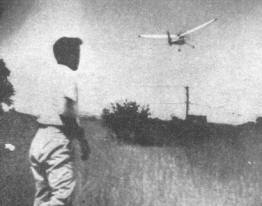
Away in a stable, steady climb. Plans for duplicating a four foot By Francis TlushIn collaboration with Gordon S. Light THIS model was designed and built primarily to test a small engine which we had just built. First results were not satisfactory. But after a new propeller had. been designed and installed the flights made us sit up and take notice. The little ship behaved even better than we had expected, .packed more of a thrill than the larger contest models. However, the fun of flying this model was destined to be shortlived. We had been flying it all morning. It had turned in one perfect flight after another. After several unsuccessful attempts to pack up and go home for lunch, we finally decided on one last flight. It was this extra flight that made us late for lunch and sent us on an unscheduled tour of the neighboring country. The motor run averaged 30 seconds, just as it had previously. But after the motor stopped the model showed no intentions of returning to the field. Instead it continued to climb on a helpful thermal and leisurely drifted toward New York City. We continued to follow it as far as Jersey City, where it disappeared high in the sky leaving no clue as to its ultimate landing place. The stop watch showed 54 minutes up until the time of disappearance. And no news of the model has ever been received despite the name and address being clearly marked on the fuselage. Fortunately, photographs had been taken that morning. Such thoughtfulness is praiseworthy. Usually the model has disappeared before you think seriously of photographing it. Construction follows the general methods used in building a simple rubber-powered job. The size of the model should fit the requirements of the rubber modeler who is beginning to branch out into the gas-model field, and the relatively small cost of materials will help bridge the gap between the cost of rubber models and the large gas ships. CONSTRUCTION The first step is to lay out the full size view of the fuselage side-panel and also the top view of the wing and tail. 3/16" square balsa longerons are used throughout the fuselage. The front motor mount bulkhead is 1/8" hard plywood. The bulkhead is dimensioned in the drawing and fits the front of the fuselage. No specific dimensions are given for the motor mount. This detail will depend on the type of motor you intend to use. Motors with radial mounting can be bolted directly to the front bulkhead with the gas tank extending back into the fuselage. This practice permits the use of a shorter motor mount, which is less likely to break and is lightweight.
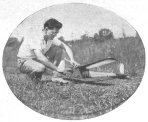
Francis TIush starting the engine. The size of the
Motors with the conventional mounting flanges can be attached to hardwood motor mounts extending from the front of the fuselage. These mounts are 1/4 x 3/8" and pass through the front bulkhead and are further secured to the fuselage structure with crossbracing of 3/16 x 3/16" balsa. The bottom of the motor is cowled, using a block of balsa carved to fit the bottom curve of the crankcase and fairing into front bulkhead. Cement this block directly to the bulkhead. The shaded portions of the fuselage are covered with 1/8" sheet balsa. It's important to keep the two top fuselage longerons perfectly level. They serve as convenient reference lines when determining wing and tail settings. Note also that no cross-braces are used at the top of the fuselage at the wing position. This will make it possible to put the ignition tray into the bottom of the fuselage. The bottom of the fuselage is floored with 1/8" sheet balsa as a base for mounting the ignition tray. The entire fuselage is covered with a light grade of bamboo paper. Spray with water and dope after the paper has dried. Rubber bands hold the ignition tray to the bottom of the fuselage. The bands pass over the top of the tray and through the sides of the fuselage covering, extending down and around the bottom of the fuselage. The holes in the bamboo paper are reinforced with several extra layers of paper given liberal coatings of cement. WING The ribs are cut from 1/16" flat balsa. First they are attached to the 1/8 x 3/4" main spar. Make the wing in two halves and join after each half has been completed. Line up the ribs on the spar and cement in place, adding the leading and trailing edges. Wing tips are merely blocks of balsa shaped to fit the end rib. Cement to the end ribs and then carve to any desired shape. The wing halves are joined by pieces of 1/16" plywood cemented to both sides of the spar. The leading and trailing edges are butt-joined with liberal coatings of cement. Bamboo paper is used for the covering. The bottom is covered first to facilitate cementing the paper to the cambered undersurface of the wing. The paper is first cemented to the trailing edge and onto the ribs as far forward as the spar and is then cemented to the leading edge. The top of the wing is covered -- paper being cemented to the leading and trailing edges only. Spray the bamboo paper with water before doping. TAIL SURFACES 1/8" thick balsa is used throughout the tail surfaces. Ribs are of flat section with sharpened leading and trailing edges. The rudder is simply a portion of the elevator as indicated by the dotted line in the drawing. After completing construction of the elevator and rudder, join then with cement. Set the rudder at zero. The tail unit is then cemented flat atop the fuselage. Or if you prefer a demountable tail, mount it to the fuselage with rubber bands. The fin underneath the fuselage is made with 1/8" sheet balsa carved to a streamline section. 1/32" wire is cemented to the outline of the fin to protect it against wear, since this fin serves as a tail skid. LANDING GEAR 1/16" music wire is used for the landing gear. The landing impact is absorbed by two 1/4" diameter maple dowels. The landing gear wire passes through these dowels, which are attached to the fuselage. Experience showed that airwheels available for rubber models of this size did not stand up under the increased weight. The size of airwheels available for gas models proved too large and bulky. Consequently, plywood wheels were substituted. While they're not as attractive, they'll stand considerable punishment. Use 1/8 " hardwood plywood with 1/4 " diameter dowels for the hubs. Drill the hubs to receive the landing gear axles. FLYING Make sure that all surfaces are perfectly straight. Should a warp develop, it can be removed by giving the wing or tail a coat of dope thinner and twisting the wing against the warp, holding the wing in this position until the dope has dried. The model should balance slightly tail-heavy. The motor is slightly offset against torque. This adjustment will result in a straight level glide after the motor has cut. This straight line flight is desirable for short test hops. But if you want to risk your model for a little thermal soaring, give the rudder a slight turn for a circular glide. MOTOR OPERATION Ignition is even more important in small motors than in large ones. The breaker points should be carefully adjusted until smooth operation is obtained. Oil and gas mixture should be varied until you're satisfied that your motor is turning up smoothly. Engine manufacturers usually include definite instructions regarding fuel mixture. Mounting the motor is especially important from the standpoint of reducing vibration. Small motors are especially sensitive to vibration. Unless it is reduced to a minimum, operation will be rough and uncertain. LIST OF MATERIALS Fuselage
Wing
Elevator
Rudder
Additional Items
Scanned From May 1938
|