|
A High-Performance Gas Model combining light PART I
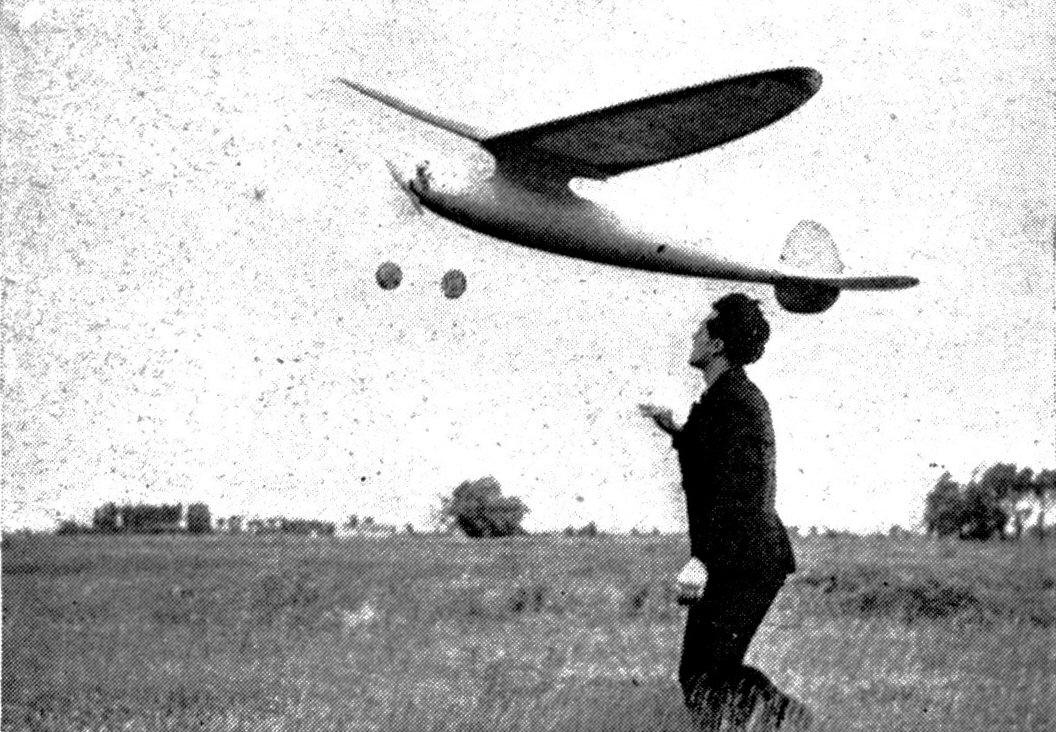
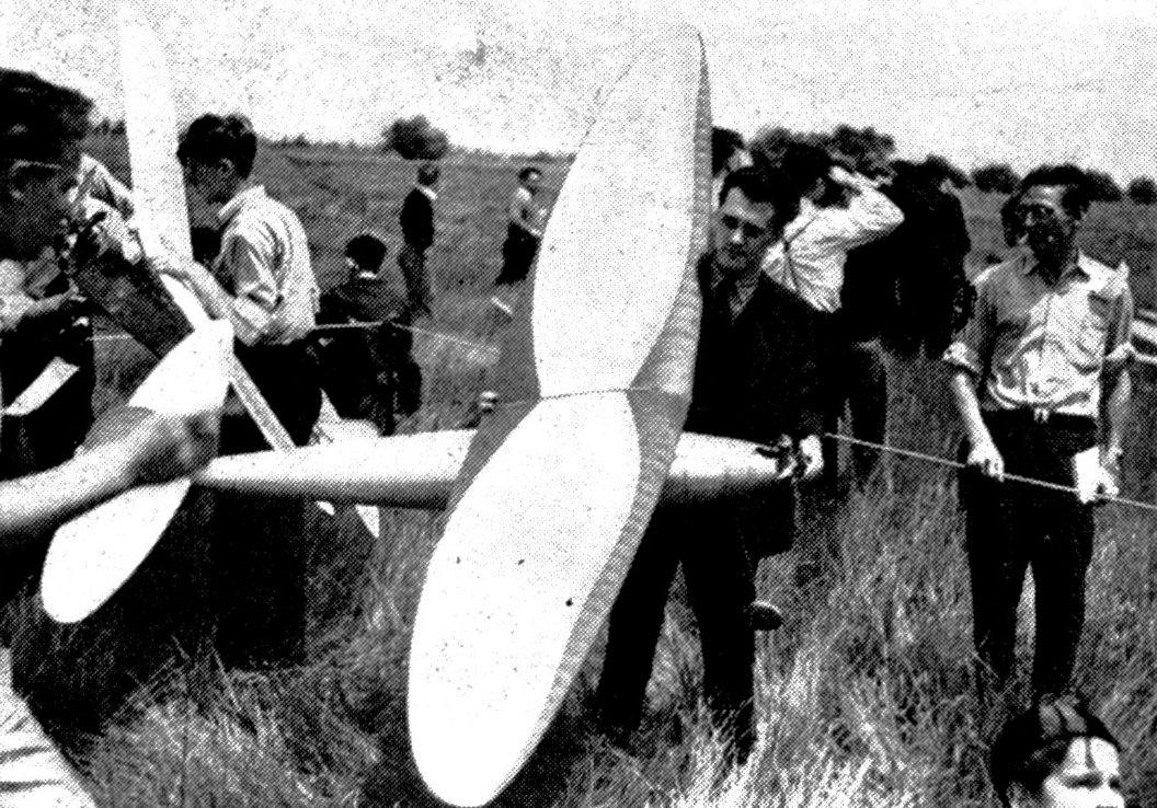
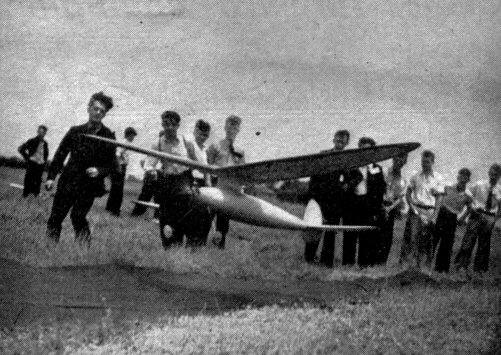
THE Valkyrie is one of the most prominent models the hobby has ever produced. It is a pleasant combination of excellent design and clever construction -- proving that an ultra-streamline model could be made lightweight. Beginning in the spring of 1936, much work was spent in design. Actual construction got under way in July and continued more or less steadily to February, 1937. The first test flight was on March 7th, lasting 4 minutes. The final flight was July 11th, taking 2nd place at the 1937 National Meet in Detroit. The Valkyrie was lost in Canadian territory after 53 minutes. And that was the last news of the model. During its short life it turned in 29 flights under a wide variety of flying conditions. Fortunately, complete data and photos had been kept of the ship. Specifications of the model are: span 10 ft.; length 8 ft.; weight with Brown Jr. (ready-to-fly) 4 lbs., 12 oz.; and a wing loading of about 5.85 ozs. per sq. ft. The glide was considered flat by modelers who watched its performance. The ratio was about 12 to 1 -- a conservative estimate which falls somewhat below the astounding ratios credited to other models. However, the Valkyrie was well able to match the glide of other championship models, proving builders are prone to misjudge glide ratios. Spiral stability was excellent because of the high center of lateral area. It showed the highest resistance to spiral diving, never going beyond a moderate bank. Notice that in the take-off photos, the wing tips are level in spite of the gusty wind. Directional stability was good with a rudder area of only 6 per cent. Undercambered stabilizer worked like a charm! The more power developed by the motor, the better it held the model under control. Modelers who watched the Valkyrie at Detroit last year might wonder why it stalled so much during the glide. The explanation fixes the blame on the flyer, since the model was adjusted with the center of gravity at 55 per cent back from the leading edge of the wing instead of the 45 per cent previously found best. But even this bad adjustment couldn't make it stall during the climb. The undercambered stabilizer did its work effectively. However, after the power cut off, the model stalled almost two hundred times during the 53-minute flight. After every two or three stalls, it would make a tight circle and come out of the stall, gliding fine for a while until the bad center of gravity location would take effect and cause a repetition of the procedure. The thrust line was set at absolutely zero-zero. No bad effects were ever noticed because of its low position. The model flew with a variety of motors. The first sixteen flights were made on a Mighty Midget, the next four on a Gwin Aero, and the next nine on the Brown Jr. Goldberg borrowed the Brown motor from Vernon Boehle the day of the meet and lost it for him a few hours later. (Note: Boehle had a new Brown Jr. a few weeks later.) In the photos the Gwin motor is being used. Construction details of the Valkyrie will be divided into two installments. Part I will include the fuselage, motor installation, and landing gear. Part II, appearing next month, includes wing, stabilizer, rudder, wing mount, assembly, and flying. FUSELAGE Figure 1 shows a box framework built from 1/8" sq. hard balsa. This framework resembles any other square sided fuselage and is built the same way. First make two identical panels and join together with cross-braces. In laying out the shape of the box framework, no special care need be taken other than keeping the 5" maximum width and the 2" at the front. This framework is covered, by the bulkheads and stringers and its shape does not influence the shape of the finished model. The dimensions included in Fig. 1 serve as an approximate check. Figure 2 shows the box framework with the bulkheads added. The bulkheads are all circular section -- the diameters of each being indicated in Fig. 2. Carl used a circular cross-section because it has far less surface than an ellipse and considerably less drag. And, too, it makes construction easier. Cut out the circular bulkheads from 1/8" sheet glued edge to edge to make up the width. (The bill of materials calls for 2" wide stock to be cemented together). Cut out the center square and hand-fit the bulkhead to the box framework. Check the width of your framework at the particular station before cutting away the center of the bulkheads. Former #2 is different from the others and is shown in Fig. 4 (full size). Its duties are manifold. It carries the landing gear, the motor mounts, and serves as a fire wall. Construction consists of two layers of 1/8" balsa cemented cross-grain plus outer laminations of 3/64" 3-ply birch plywood. The square opening in the box framework is filled with this same type structure. Two holes are cut in bulkhead #2 to accommodate the motor mounts. A third hole (1/2" diameter) is cut in the bulkhead for the battery leads. Bulkhead # 1 is also shown in Fig: 4. All other bulkheads with the exception of #2 follow this type construction. Figure 3 shows the stringers (1/8" sq. hard balsa) added to the fuselage structure. Twelve stringers are evenly spaced around the bulkhead and set in notches. At the rear of the fuselage the stringers are joined to form the rear tip of the fuselage, which extends 4-1/2" back of the box framework. WING MOUNT FLOOR Flooring is a piece of balsa 1/8 x 1-1/2 x 16-1/2" which runs through the top-center of the fuselage. It is anchored with 1/8 x 1/4" balsa running across the bulkheads. After the fuselage has been sheeted, holes are drilled through, the skin and floor to take the wing-mount spars. (To be described next month.) LANDING GEAR A single piece of 1/8" diameter wire is bent to the shape indicated in Figs. 4 and 6. It is bolted to bulkhead #2. Fittings are bent from .020 half-hard aluminum. Use 3/32" diameter machine screws. Wheels are turned to elliptical cross-section from hard balsa 1" thick and 4" diameter. Insert 3/16" diameter aluminum tube bushing through the center. Collar with set-screw fastened on each axle-end. The tread of the landing gear is about 18" and the centers of the wheels should fall directly below bulkhead #1. COVERING Cover the entire fuselage with balsa planks 1/16 x 1/2". Cement the planks to the bulkheads and stringers. Match the edges of the planks to make a tight fit. Toward the ends of the fuselage it will be necessary to taper the width of the planks. The list of material calls for 36" length planks. When joining the planks lengthwise, put the joint at a bulkhead and make sure the curve of the fuselage is not interrupted. After planking, the edges can be rounded off with sandpaper until the covering is smooth and symmetrical. Treat with several coats of dope to protect the wood. A more detailed description of the methods of finishing will be described next month. HATCH AND DOOR Figure 5 is a sketch of the front part of the fuselage showing the portions which are cut away. The hatch is the upper half of the fuselage between bulkheads #1 and #2. The door is between #2 and #3. (It can be put on either side). A battery box is built between #2 and #3 bulkheads. This installation as well as the motor installation will vary with the type of equipment used. A typical method is shown in Fig 6. 3/16" x 1" balsa is used for the battery box, and the batteries extend across the fuselage. The battery door is hinged to swing down. Hinges are .034 piano wire. Clothing snaps are used to fasten the door at the top of the fuselage. Batteries are accessible through this door. MOTOR INSTALLATION Sugar pine motor mounts are cut to the shape shown in Fig. 4. They extend through the holes cut in bulkhead #2. In addition they are cemented to # 1. A balsa nose block (shown full sue in Fig. 4) rounds out the front of the fuselage. It is notched to fit up underneath the motor mounts. It is cemented to bulkhead # 1 and to the motor mounts. The hatch is cemented back in place after the motor is mounted. Cut away the top portion to allow access to the needle valve, air intake, gas tank, etc. If it is necessary to service the coil and condenser mounted directly behind the motor on the motor mounts, the hatch can be removed by cutting the cement with a sharp knife. Next month we'll continue the construction of the Valkyrie. In the meantime finish up this month's work so you'll be all set to start wing construction. MATERIAL REQUIRED
Scanned From September 1938
|
|||||||||||||||||||||||||||||||||||||||||||||||||||||||||||