|
NATIONALS A good flying scale job should BY ROGER HAMMER
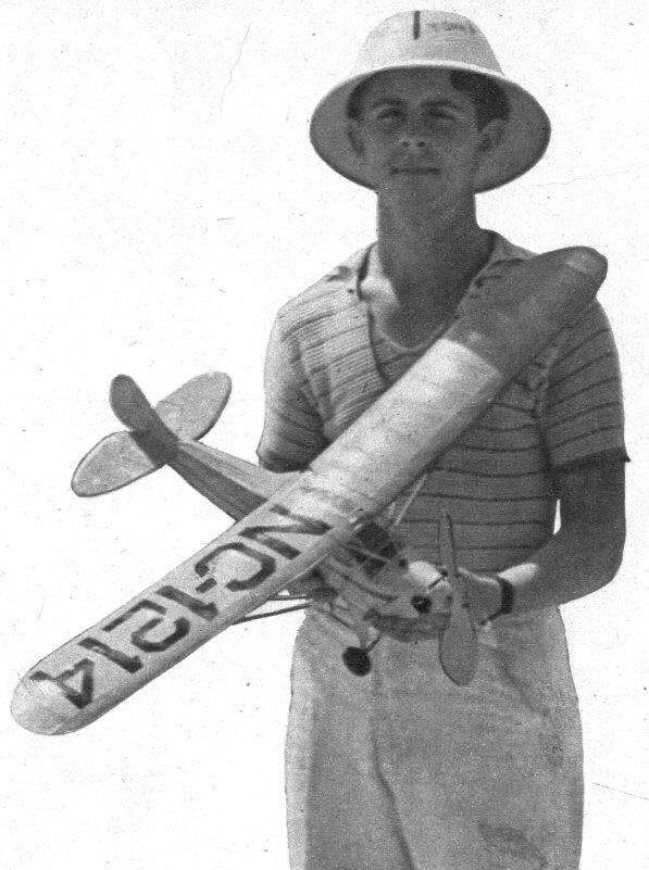
FLYING scale models have always been popular, especially among beginners, since they look so much like their prototypes. If one should look at the list of entries at the National meet, however, he would undoubtedly think that flying scale model builders are few and far between. Such is really not the case. Many model builders who attend the Nationals each year have built and flown flying scale models, yet they seem to forget that particular type when building their ships for participation in the annual brawl. Why? The answer is simple. A model builder thinks that he has to have something more or less exceptional if he is to place among the "big-name" builders, so he thinks of a very clean design that will take a lot of time to build. In doing so, he does the reverse of what he should do. The correct way of going about this flying scale business is to choose a simple, easy-to-build and easy-to-fly model, and to make it strong. The strength is very important if the model is to stand up under all the abuse a flying scale model is subjected to when testing and flying under adverse conditions. The Taylor Cub (the 1937 Cub, then manufactured by Taylor), while not as clean as some military designs, makes up for this by its strength, which is almost unbelievable. The square fuselage construction allows as much strength as in a cabin type fuselage of the same size, permitting the use of a powerful motor for top performance. If you have intended building a flying scale model for a forthcoming contest, consider the Taylor Cub. Its fine performance in almost every flying scale meet entered, and proven stability when built as The original Cub model had to be packed in a small model box, therefore, the wing and wing struts were made so that they could be removed at will. This is not necessary if you have the room to stow away a three-foot model in your car or model box. After you have read the building instructions and looked over the details on the plans, you should try to remember to use heavy balsa in the front of the model and medium balsa in the tail surfaces, so that the model will not be as tail-heavy as the original. Since the model has to weigh at least 5-1/8 ounces, it is best to put some of the weight into the fuselage and landing gear structure. The main fuselage structure should be made first, by building both sides of the fuselage right over the fuselage side view drawing. While the sides are drying, the cross braces should be cut to double the length shown in the top view, as only the right half of the fuselage is shown. Since the bottom of the fuselage is perfectly flat behind the landing gear, the cross pieces should be inserted in place after the two sides of the fuselage have been pinned down to a drawing similar to the top view drawing. The rear cross braces should be cemented in place first, and after nearly the whole fuselage is complete, the front part should be cracked slightly ahead of the landing gear portion, and cemented. Note that the sides "toe in" quite sharply here, so reinforce this part with a few extra coats of cement. When applying formers F1 and F2 to the top of the fuselage, note that F2 is slanted forward. After the fuselage frame has dried and the stringers behind the wing portion have been added, the front should be covered with 1/32" sheet. Do not forget to cover the fuselage bottom up to the part where the rear landing gear strut meets the fuselage. In making the landing gear strut fittings, use wire about .049" in diameter and brass or aluminum tubing that fits snugly. After the small lengths of tubing have been cemented to the fuselage, they should be reinforced by cementing small staples in place. Remember that the celluloid in the side windows should be cemented inside the cabin, after the balsa has been color-doped. In making the landing gear strut, the following method should be used: Bend the V-shaped part fist, and bend in the upper ends. Insert these upper ends into the short lengths of tubing on the fuselage, and build up a triangle of balsa to fit inside the strut. After cementing well, the strut should be covered with silk. Balloon-type wheels should be used for maximum shock-absorbing qualities, but the landing gear can take any shocks by using the rubber band spreader in the center. The band should consist of about five small loops of 1/32" rubber inserted in the hooked end of each axle bar and passed through the V strut that has its ends cemented to the side fuselage longerons. The axle bar should be bent at the tip to retain the wheel, but a neater appearance can he had by soldering a washer in place. An ordinary bushing is cemented or soldered in place on the other side of the wheel. The nose block should be carved out of a small hard balsa block, and the cylinder details added. The cylinders are merely 5/16" dowels wrapped with thread, and the cylinder head is 1/16" sheet balsa cut to the shape shown in the side view of the fuselage and covered with lengths of thread arranged horizontally. The engine, gas gauge, and air intake tube should be added only after the fuselage has been doped. The details are all black, and should be cemented in place after they have been color-doped. The nose plug should be a snug fit so that it doesn't drop out of place in flight due to a slack motor. The rubber tensioner may or may not be used, according to the weight of the finished model. If the model is too light when weighed with the motor, prop and all the parts assembled, a tensioner device should be added so that a longer motor can be used to bring the model up to weight rule. No instructions will be given concerning the construction of the tail surfaces, as they are of simple flat construction, utilizing 1/8" sheet outlines and 1/8" by 1/16" ribs and spars. Most of the wing is given full size, and all that is necessary to complete it is to cut the plan at the proper place and separate the two parts until the space between the innermost ribs of each section is 9". This space should be divided into six spaces of 1-1/2" each, completing the layout of the entire left wing panel. Note that the end of the wing spar is tapered, allowing the tip portion to be built at a slight dihedral angle. If it is not necessary to remove the wing when transporting the model, the wing can be cemented in place permanently and the wing struts cemented in place also. If the wing is to be made removable, the wing struts should have a tubing and wire arrangement whereby they may be slipped into place for flying and slid off when the model is ready to be packed away. The motor should not have any slack if the model comes up to weight rule when assembled, as a tight motor has much more power than a loose one. If the model is too light, the rubber tensioner device should be used. On the original, it was necessary to add 8" of slack rubber to bring it up to weight rule. A small amount of clay was placed in the nose also, as the wing could not be moved for adjustments. A motor consisting of sixteen strands of 1/8" should give this model enough pep to get it upstairs in a hurry. A freewheeling of the Garami type should be used to extend the glide to the best angle possible. The Cub should be adjusted to fly in right circles under power and in the glide. Well your model is finished, so-happy landings! Scanned From April 1940
|