|
THE LITTLE JUNIOR
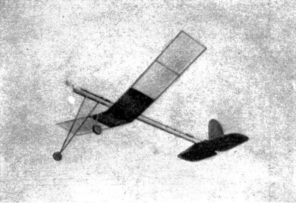
THIS model lays no claim to unusual performance or unique construction methods. But it does make a bid for the attention of the beginners as an easy-to-build-and-fly model of sound design. All parts are numbered and listed in the bill of materials and should be readily available at any model supply shop. CONSTRUCTION The motor stick (#1) is the "backbone" of the model -- serving as attachment for the motor, tail, landing gear, and wing. Select hard balsa to avoid excessive bending when the motor is fully wound. The thrust bearing (#2) can be made or bought in a variety of different shapes and materials. The most conventional is dural, but a drilled brad or bent wire bearing makes an effective substitute. Rear hook (#3) is bent from 1/32"-diameter wire and threaded and cemented to the rear end of the stick. The landing gear is made up of four pieces of bamboo (#6 and #7) with the ends pointed and inserted into the motor stick. Apply cement liberally to hold them in place. A wire axle (#8) is threaded and cemented to the ends of each V of the landing gear. Hardwood wheels (#9) of 1" diameter are slipped on the axles -- the ends of the axles being bent to hold them on. A tail skid is bent from bamboo (#5). Bamboo is most conveniently formed by bending around a hot soldering iron or curling iron. Or an old screwdriver can be heated over the gas-stove flame. Wing is made in two halves. Spread a piece of wax paper over the work table to prevent cement from sticking. The inside-center panel of each half of the wing is filled in with 1/32" sheet (#15) set flush with the top edge of the spars. Cement the two halves together -- blocking up each tip 2-1/2" for the necessary dihedral. Elevator is cut from a piece of 1/16" soft sheet balsa. Only half the full-size pattern is given in the drawing. Cut the elevator in a single piece by turning over the pattern and tracing the other half. A slot is cut in the center for the tail skid. Cement the elevator firmly to the bottom of the motor stick. Balsa cross strips (#20) are cemented to each half for additional strength. Rudder pattern is also shown full-size. It is cemented atop the elevator and to the rear end of the motor stick. Clips bent from 1/32 "-diameter piano wire, hold the wing to the stick. These clips are shown full-size and should fit the motor stick snugly. The rear clip (#18) should be 3/32" higher than the front (#17), giving the wing this amount of incidence. Cement these clips firmly to the two spars at the center of the wing. Propeller is cut from a soft balsa block. The blank should first be shaped as indicated in the drawing. Punch a hole through the exact center with a needle. Blades should be rounded at the tips after cutting. Blade thickness should vary from about 3/8" at the center to 1/16" at the tips. Reinforce the hub of the propeller against wear from the shaft by coating liberally with cement. The shaft (#11) should first be inserted through the thrust bearing and three small brass washers (#12) inserted between the propeller and the bearing. The shaft is secured to the propeller by bending a U in the end and pulling back into the front hub and securing with cement. Rubber motor is made up of four strands of 1/8" flat. However, don't hesitate to add additional strands if your model seems to lack the necessary power for a fast, high climb. Covering is conventional tissue. Cover the sheet balsa portions of the wing and tail as well as the remaining portions of the wing. Apply dope only to the edges -- a full covering will more than likely cause the wing to warp out of shape. FLYING Flying should get under way with a few trial glides, having the wing in the approximate position of the model in the photographs. Always point the nose of the model toward the ground at a slight angle, and follow through with a firm, steady push. If the model falters and then dives toward the ground, make adjustment by moving the wing toward the propeller. Make adjustments slowly. Never move the wing more than 1/4" forward or backward without making a test glide. If the model dives toward the ground without showing any tendency to climb, move the wing toward the tail. Power flights should first be tried with about fifty turns in the rubber. This will be enough power to detect any serious misadjustment. The turns can be increased as the trial flights prove the setting to be satisfactory. Never point the model upward when launching. Hold it level and push it at the speed at which it normally flies. If you're not too sure of your ability to launch it properly, let it take off from a smooth surface. If the model shows a tendency to spiral sharply to the left and lose altitude quickly, warp up the front spar of the left wing (looking from the rear). At the same time turn the rudder slightly to the right. A model will show a tendency to spiral to the left more often than to the right since the reaction to the turning propeller depresses the left wing. Despite its single-surface wing, Little Junior is a nice performer. In fact, two were built before the plans were drawn and both were flown out-of-sight. BILL OF MATERIALS
Scanned From August 1939
|
|||||||||||||||||||||||||||||||||||||||||||||||||||||||||||||||||||||||||||||||||||||||||