|
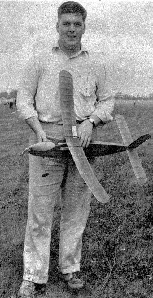
1939 This model's 36-minute flight won the Stout Trophy and qualified the builder as captain of the American Moffett team.
BY BOB TOFT THIS is a typical American model. It was finished at five o'clock in the morning, a few hours before it won first place in the Minneapolis Model Aero Club's eliminations for the Nationals. It won for the builder an all-expense air-lines trip to Detroit, where he gained the Stout Trophy. The 12-3/4-minute average of three flights that the model hung up was one of the outstanding marks of the contest. The model is extremely simple, and the inclusion of full-size parts in the plans should make every beginner reach instinctively for his favorite razor. CONSTRUCTION Fuselage. A plan view of the fuselage should be drawn up. All measurements are given on the plans, but any not supplied may be had by multiplying the size of the part on the plan by four, the plans being one-quarter full size. Two sides of the fuselage should be built simultaneously to insure duplicate shapes, and after the cement has dried they should be removed from the drawing and checked. If one or both of the fuselage sides has warped out of line, insert one or two diagonals in the proper places to straighten it out. The two fuselage sides should be connected at the extreme rear and the cross braces added. If rubber bands are stretched around the fuselage after two opposite braces have been added, the next two may be cemented in without waiting for the last set to dry. The landing gear is bent to shape and embedded between the full-size gussets given on the drawing. After the nose and tail ends of the fuselage have been filled in with 1/16" sheet balsa, the corners of the longerons are sanded slightly round and the fuselage covered with tissue. Wings. After nineteen ribs have been cut from 1/16" balsa, bamboo wing tips are bent to the outline shown on the full-size plate. After assembling the entire wing, the bottom spar, leading, and trailing edges should be cracked slightly for dihedral. The top spar and sheet covering will have to be cut out a little to provide the necessary gap to be taken up by the wing when the tips are raised. When covering, make sure that the wing does not warp. If the shrinking of the tissue after it has dried causes a warp, it can be removed by holding the wing in the proper position while doping. Tail. The stabilizer is made in much the same manner as the wing, and it also should be free from warps. After it has been assembled and covered, cement it to the tail plug at the proper angle, a small incidence block being cemented under the leading edge. The incidence block should be slightly more than 1/8" thick. The rudder is flat, having been built up from 1/8" square and 1/8 x 3/8". When cementing the rudder to the top of the stabilizer, offset it slightly, as the model is intended to fly in large circles. The wing mount and nose plugs are illustrated in detail. Be sure to brace the tail plug securely, and the cross pieces it is cemented to should form a T section. Propeller is carved from a medium-hard 2 x 2 x 9-3/4" block and should be doped and then sanded with successively finer grades of sandpaper. After the hinge parts have been carefully cut and bent to shape, they are cemented to the prop in the proper position and bound with thread. Three or four coats of cement should follow on the bound portion to insure long use with little fraying or wear. The counterweight should be oversize, so that it may be trimmed down to balance. In cutting the prop at the point at which it folds, a very fine jig or scroll saw will not rip the wood excessively. In positioning the prop for folding, the nose plug should be inserted so that the stop is in such a position that the prop folds flat against the left upper fuselage side (looking from the rear). The motor used in the original was composed of twenty strands of 3/16" rubber, 50" long. A good grade of lubricant should be used, and it is necessary to employ rubber tubing on the prop hook and rear hook. FLIGHT The original model was adjusted by setting the wing and tail at a definite angle to each other -- two degrees angular difference -- and maintaining that relation during all adjusting. The wing was shifted to produce the best glide possible. The center of gravity was about an inch behind the trailing edge of the wing when the best glide was had. The wings were perfectly straight with no warps for adjustment. The rudder was warped slightly for a right turn. The nose plug was offset to produce the correct climb adjustment. The model did not climb very fast, but a long motor run gave it more time to strike a thermal. Even without the help of thermals, the glide stretched out the time pretty well. The model circles to the right under power and in the glide. The circles are about one hundred feet in diameter, because the designer thinks that too tight a circle will induce an unnecessarily steep glide. The maximum turns are twelve hundred, a few of which remain after the prop has folded. BILL OF MATERIALS
Scanned From December 1939
|
|||||||||||||||||||||||||||||||||||||||||||||||||||||||||||||||||||||||||||||||||||||||||||||||||||||||||||||||||||||