|
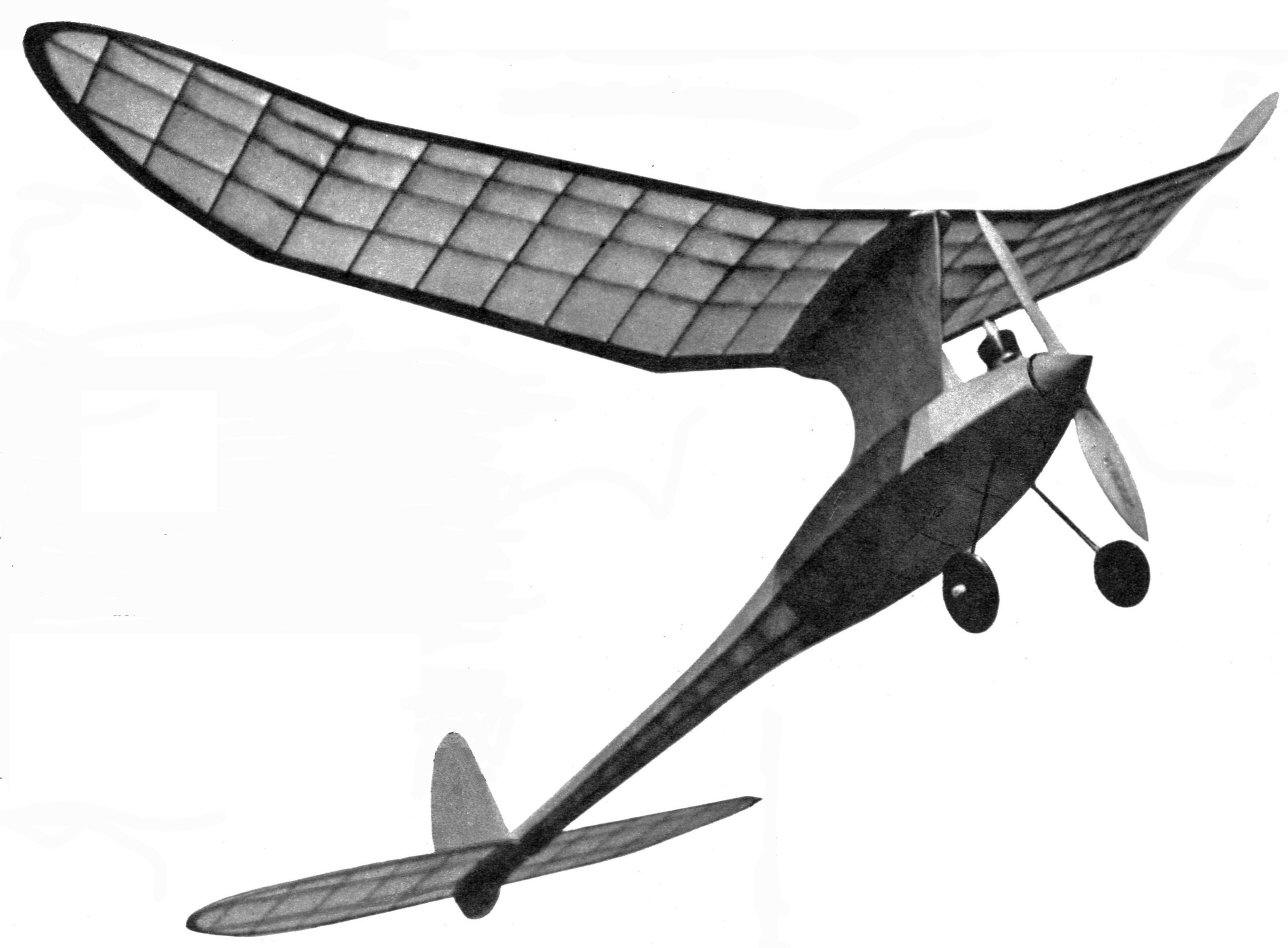
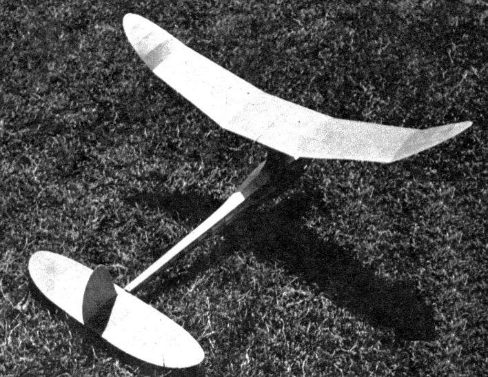
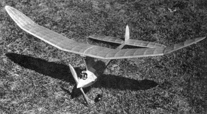
Snuffy 6th There isn't a gas job that can outstep Snuffy! Five years' development makes it a high scorer. It's good for 1:20 on an 8-second motor run. BY ROBERT TOFT
THE Snuffy series, of which the model presented here is the sixth, was started in 1937. The distinguishing feature of all models in this series has been the "pod and boom" fuselage construction. Snuffy II was built in 1938 and in three contests entered won two firsts and a third. The fourth, fifth, and sixth of this series were built in 1940. Snuffy IV was an Atom-powered model of about 190 square inches of wing area. Snuffy V was a fairly large Class C job powered with an Ohlsson "60." Although it had a fast climb and a very beautiful glide, a series of minor accidents, such as encounters with barbed-wire fences and telephone wires, prevented any real success with the plane. Snuffy VI, as presented here, was finished in August, 1940. It showed early promise by placing third in a "dawn" contest with an average of 2 minutes, 12 seconds. A fellow club member, Bill Bennett, built a Snuffy soon after and both his and the original were entered in the fall meet of the Minneapolis Model Aero Club. Bennett's model and the author's placed first and second respectively in Class A. On June 16, 1941, the original model was entered in the Nationals eliminations of the Minneapolis Model Aero Club and on two flights of 4 minutes, 12 seconds, and 8 minutes and 15 seconds, placed first in Class A. The 8-minute flight was the original Snuffy's last, as it disappeared from sight and ended up in a farmer's yard about twenty miles south of the take-off point and was not located for over a month. It was found after the farmer had cut past it with his mower. Bill Miller and several other Sioux Falls, S. D., boys have built the Snuffy and have had good results with it. In a single day's flying Bill had flights of 10 and 13 minutes with it. Although the Snuffy may seem large for Class A, it was designed around the Bantam engine. The Bantam, because of its high power and low weight, is especially suited to the model. Ohlsson "19" and "23" motors have been used with good success in the model, and if an A and B combination is desired, these engines should be used. As an indication of its performance, the Snuffy would turn in flights of 1 minute, 15 seconds to 1 minute, 20 seconds on 7 and 8-second motor runs in dead air. CONSTRUCTION Before giving structural details of the Snuffy, a word about materials and workmanship. The original model was built of eight-pounds-per-cubic-foot Jasco balsa, and the use of this weight is recommended. If you build this model, spend a little time on it. Finish all parts carefully and you won't have to depend on the covering to hide sloppy workmanship. The soundness of the general design and construction of the wing has been thoroughly proved by Carl Goldberg's gas models. A procedure for wing assembly that has proved satisfactory is as follows. Cut all spars and leading and trailing edges to shape, tapering them as shown on the plans. Cut and slot all ribs. Build the wing in five sections. Pin leading and trailing edges to the plan and glue ribs in position. Slip spars into slots and tack-glue. When dry remove from board and reglue each joint. Rough-shape the leading and trailing edges and join the individual sections with the proper amount of dihedral. When the wing is a single unit; finish cutting and sanding leading and trailing edges, making sure that there are no bumpy spots and that all spot blend smoothly. The completed wing has 300 square inches projected area and should weigh close to 2 ounces. The stabilizer is built like the wing except that it is a single unit. Note slot for base of rudder located in the center of the stabilizer. When spacing ribs for this slot, use rudder or pieces of rudder material for spacers. The rudder is cut from 1/8" sheet balsa and is sanded to an airfoil section. The tab is held in place by thin aluminum hinges. The completed tail assembly should weigh about 3/4 ounce. The fuselage base consisting of formers and stringers is built first. Cut out and notch former halves. Cut out eight master stringers by making the pattern of the fuselage outline and then cutting , stringers from 1/16" sheet balsa in the same way indoor model ribs are cut. Lay two stringers on plan and glue all former halves in place with the exception of Former 1. Add one side stringer. When dry remove from plan and add Former 1, remaining half formers and other side stringer. At this point the landing gear, motor mount, and complete ignition system should be installed. The landing gear is bent from 3/32" wire, and is fastened into a groove on the edge of a piece of 1/8" plywood and bound with thread to the plywood. The motor mount is cut from .050" aluminum and is bent as is shown on the plans. Both landing gear and motor mount are held to the front bulkhead by four bolts which screw into nuts embedded in plastic wood on the rear of the first bulkhead. On the original model all parts of the ignition system were permanently fixed in place. It is the author's belief that a permanent system which is well made will give less trouble and better ignition than a removable system. In almost a year of steady flying the ignition system on the original did not have to be touched. Keep all wires as short as possible and solder all connections, using a noncorrosive flux. The drawing gives position of various parts of the ignition system. After the internals are installed, the remaining four master stringers may be added. Following this, glue a strip of 3/32" square balsa over each master stringer. The wing mount, built up of three sheets of 3/32" sheet balsa shaped as in the drawing, should be installed at this point. Shape wing and tail platforms and glue in place. Fill in nose section of fuselage and section just forward of the tail platform with 3/32" sheet balsa. Glue a 1/16" sheet containing a half-inch hole for timer knob over the timer position. The area over the Austin battery box is not covered with paper but a celluloid hatch is taped in place after the batteries are installed. The fuselage can be covered very quickly and easily if the following procedure is used. Make a pattern of cardboard or sheet balsa that will just cover the area between two cap strips. Fold a piece of covering material eight times and cut around pattern. This will yield eight covering sections. Using these, no piecing or cutting will be necessary during the covering process and a beautiful job can be done in a very short time. The cowling on the original model was made of paper. On the model of which photographs are shown, the cowl is built of a stringer and bulkhead system covered with light sheet balsa. Of course any desired cowling material may be used, but it should be remembered that on this model the cowling is merely a fairing and assumes no load. For this reason it should be kept light to eliminate excess weight. The paper cowl may be made by gluing narrow bond paper strips over a waxed balsa block shaped to the nose of the model. The original model was covered with rubber model Silkspan. Either this material or single tissue is recommended. On a model of this size there is little to be gained (except weight) by using double tissue, bamboo paper, or silk. Give fuselage about five coats of half-and-half dope and the wing about three. With the ignition system fixed and with the wing permanently located, there might be some doubt about the balancing of the model. It so happened that the original model needed no balancing. To eliminate any chance of unbalance the model can be completely finished except for covering on the fuselage and then balanced. If any unbalance is noted the batteries can he shifted to correct this. When the model is balanced make all further adjustments with stab and motor. The model should balance five inches behind the leading edge of the wing. The model can be adjusted to fly with or against torque as the builder chooses. In any case adjust the model to circle in the same direction in the climb and glide, to eliminate dip. No downthrust should be necessary. Adjust for flat glide with stabilizer. Fly model under low power at first and adjust glide circle as desired. Then offset thrust line of motor to obtain a similar circle under power. Engine offset is easy to accomplish, due to the removable motor mount. Well, that's the Snuffy; if you like its looks build it. It's performance won't disappoint you!
Scanned from March 1942
|
||||||||||||||||||||||||||||||||||||||||||||||||||||||||||||||||||||||