|
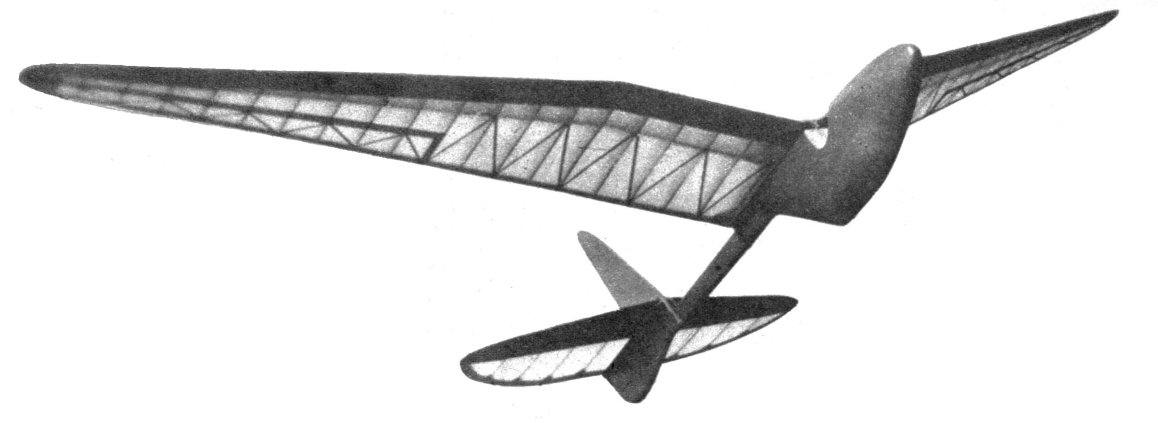
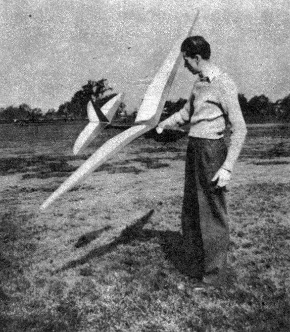
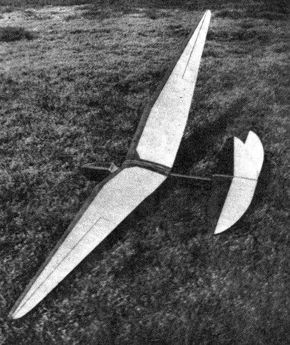
The Jersey Albatross
You don't need rubber to get 'em up thar! This super-soarer will outperform gas models. Meets NAA contest requirements.
THE Jersey Albatross is the result of three previous attempts at large glider construction and flying. The fuselage is a solid pod-and-boom construction and features a detachable landing skid. The wing is a monospar, gull-wing design having sufficient dihedral and yet retaining scale appearance. Outer wing panels taper. The zigzag wing bracing and aileron construction are false and were built to further the scale appearance of the model. In flight it resembles a ship combining features of the Baby and Super Albatross soaring gliders. CONSTRUCTION Draw up a full-size working plan of the fuselage. Note that the typical cross section of the fuselage consists of a piece of 9/16" rock-hard balsa sandwiched in between two pieces of thick medium balsa. From the plan, trace the outer border of the fuselage only on a piece of 1" thick medium balsa. Cut out two identical sides. Study the plan and determine the outline of the three pieces of 9/16" stock which are required for the center of the fuselage and extending the length of the boom. Trace these pieces on 9/16" stock and cut out. Cement these to one of the outer sides. Cut the two plywood sections and cement in place. Be sure to have a 1/16" space open so that the removable landing skid (1/16" wire) may fit snugly in this compartment. The other side is then cemented to the middle pieces. The end of the boom is slotted eight inches in from the end. This slot, running parallel to the boom, is cut to accommodate 1/8" sheet and can be made accurately only by using a circular saw. The stabilizer and rudder mount are constructed as shown, and the pod and boom are carved and sanded to the correct cross sections. The cockpit is then cut out and the entire pod and boom are given two coats of wood filler and three coats of thinned-out orange dope. The weight. for balancing the model is fitted into the nose of the model later. Now for the wing. Draw a full-size working plan of this and cut out the required ribs. The center section and the two adjacent straight panels are constructed on the plan. Lightly cement the ribs in their required spacing upon the 1/4" square spar. After the leading and trailing edges have been cemented, the 1/8" sheet inserts can be cut and cemented between each rib and to the 1/4" spar. These two panels can be connected to the center section after cut-outs have been made to accommodate the 1/16" plywood center gusset No. 1. The tapered panels are made in a similar manner and can be connected to the rest of the wing after cut-outs have been made to accommodate the 1/16" plywood gussets No. 2. The center section is entirely covered with 1/20" sheet balsa. The leading edge of the panels are covered top and bottom with 2" widths of 1/20" balsa sheet. The zigzag bracing can be omitted without lessening the strength of the wing. The ribs are capstripped top and bottom with 1/20 x 3/16" strips. Entire wing is covered with gas-model white Silkspan. The sheet-covered leading edge is painted orange. The orange and white are separated by a 1/8" strip of black tissue doped onto the wing. Last comes the stabilizer and rudder construction. Draw full-size working plans. The stabilizer consists of a spar 1/8 x 1/2" on edge running the entire length of stabilizer. The ribs are 1/8 x 1/2" cemented where shown on plan. Leading edge 1/4 x 3/16" and trailing edge 3/16 x 1/2" are cut. and cemented; the end pieces are fitted by the cut-and-try system. Trim the ribs roughly to shape and sand to a streamline section as shown. Cut extra ribs and cement to center rib. Cut gussets and cement to ribs where they connect the trailing edge. The rudder consists of a spar 1/8 x 1/2" and ribs of 1/16 x 1/2" cemented to the spar. Leading and trailing edges are cut and cemented. The bottom rib is made of double thickness and cemented. This rib is cut out to conform to the shape of the middle stabilizer rib. The gussets are cemented at the base of the rudder as shown. Both rudder and stabilizer are covered with white gas-model Silkspan and doped twice. The rudder is glued on top of the center rib of the stabilizer. The spar is the boundary line for the solid-color forward portion of rudder and stabilizer. ASSEMBLING AND FLYING The stabilizer, with the rudder cemented to it, is bound to the stabilizer support with 1/8" flat rubber from the rear hook over the stabilizer and under the boom, then back to the rear hook. Lash firmly, not too tight. The main wing has a 1/8" strip of hardwood cemented underneath the center section directly under the spar. The front hook in the cockpit and the tail boom are utilized to connect rubber used in binding on the wing. Bind wing on snugly, not too tight for first test glides. Test-glide over high gross until you get the feel of launching the model. The weight of your particular model will determine the amount of balance weight needed in the nose. When this balance weight has been decided upon, it can be permanently affixed inside the nose of the model and the outside finished off smooth. Do all test flying on a calm day. For first towed flights, select an assistant to act as launcher. His job will be to hold the model aloft and point the nose up into the wind. Start off with fifty feet of kite cord towline and attach one end to the front towing hook. The launcher of the model should run forward to enable the model to acquire some percentage of its required flying speed before the towman climbs the model by holding the towline and heading into the wind. The model should be in a level gliding position before the the towline is released. Don't stall the model as you cast off the towline. The towman must look back constantly at the climbing model to be ready to slacken the towline in case the ship veers off. He should drop the towline at once if the glider veers off suddenly near the ground due to a faulty launch. Generally speaking, a hook well forward of the center of gravity is used for towing on windy days. The front tow hooks, as drawn on the plans, were used quite successfully in both calm and breezy weather. Flying should not be attempted in gusty wind. After a few tows and straight glides have been accomplished, the stabilizer and rudder can be offset a trifle to make the model circle to the left. Forty-foot circles are preferable. This adjustment will have very little effect on the straight towing of the model. The detachable landing skid may be replaced with a landing wheel if desired. However, the original model was flown on a short, cropped grassy field and skimmed in smoothly on its landing skid due to the slippery grass. The tail skid is to prevent the model from leaning over on a stabilizer tip while at rest on the ground. The model, if flown intelligently, will stand up and give many hours of sport. Scanned From October, 1942
|