|
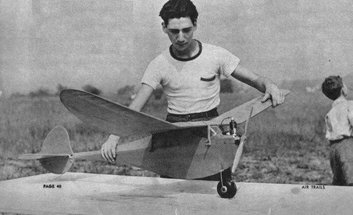
THE ROCKETEER Out-of-sight flights are regular with this ship. They
should be. WARNING: Don't build the Rocketeer unless you are strong of leg and long of wind. We've grown darn tired of chasing this ship on "average" hops, and even more weary of shagging anywhere from ten to thirty-five miles after the critter in response to cards, letters, and telegrams telling us that the plane has been found.
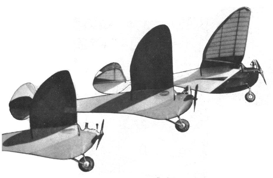
The three Rocketeers. The one in rear is Schoenbrun's,
the others are Jerry Stoloff's.
THE Rocketeer represents an evolution in design from a perfectly rotten experimental job into an ultimate in medium-size Class C contest ships. After watching "jallopies" take home the bacon in innumerable contests and analyzing their faults and their good points, the first of the Rocketeer designs was formulated. Originally we planned a ship that would have a low center of lateral area, a rather long moment arm, a low center of gravity, high thrust line, and a real pendulum effect to increase directional stability. The first of the ships had the customary wing -- with dihedral in a V form. After mediocre results this was modified until the present form of tip dihedral was evolved. The first ship had a tail moment arm that was too short, and which was subsequently lengthened. It was hard to adjust, a matter which was remedied by enlarging the "belly," giving a better placement of lateral area. The final design was built into the present ship, which was completed in the dim, dark hours of the morning of April 19th. We had entered the contest held that day at Creedmore, L.I., and everything was ready for a stellar performance, except for one small item -- the timer had not been checked. It was an old timer, erratic and undependable, and after the first test flights we knew we'd have trouble with it. But as all fliers will, on occasion, we took a chance. We paid our entry fee and the plane was sent up on an "official." The ship climbed beautifully -- almost straight up. A steep "hang type" of climb that took the spectators by storm. We had the contest sewed up, and were just about to celebrate when our timer turned aside, shook his head and muttered "Sorry, fellows. Twenty-four-second motor run. Unofficial flight." But the Rocketeer stayed up. Fifteen minutes later it was still over the field, according to unofficial timers. Gradually the higher currents took the ship and it drifted east and disappeared in the haze of the afternoon. Somebody else won the contest. We were heartbroken. Two days later we received a card: "Dear Mr. Schoenbrun," it read. "Your ship landed here at five o'clock Sunday afternoon. Please come and get it." The address was a point some thirty-five miles from the starting place. It had landed about three hours after being launched. By May 6th we were ready to enter the Rocketeer in the second annual meet of the Stratosphere Club of Passaic, N.J. Howie Beitclunann, also of the Sky-Scrapers, had built a similar plane, a duplicate to the last ounce. All morning we tinkered with the original ship, but our old motor began to act up and spoiled our chances. After three "stinky" short flights she placed only eleventh. Then we turned to Howie's ship, which boasted a new Brown. The first flight wasn't sensational-some two minutes and fifty-seven seconds, with the motor at half throttle. Herb Friedlander of our club was ahead of us, and we needed a superflight to beat him for the first-prize trophy. As a result, we made our adjustments very carefully. Howie nodded at the timer, started his motor, and opened it wide. We didn't wonder at the gasp from the spectators. We were astonished, too, for the Rocketeer literally lived up to her name. It hung on the prop and bored a hole in the afternoon sky. Later we heard that a mathematician in the crowd had (by aid of a range finder) estimated that the ship reached an altitude of some seven hundred feet on the motor run. At nineteen seconds the motor cut, then that glide, slow and shallow as the flight of a soaring bird. A thermal bounced the ship higher, and it circled slowly to the right. At the end of ten minutes and twenty seconds the Rocketeer disappeared to the south in a bank of clouds, appreciably higher than it had been on the motor run. The timer clicked his watch, handed in his time; the ship had definitely clinched the meet for us and for the Sky-Scrapers. There is a sequel, of course. Four days later we received a letter from the Bronx. Howie's ship had landed at Fieldstone, N.Y., after crossing the Hudson River. The point was some twenty-five miles away to the northeast. As we say, we're getting tired of chasing this ship. Now a brief word of description. The airfoil in the wing may be attributed to Gordon Murray, of the Sky-Scrapers, who affectionately calls it the Murray GM-l, although he admits he conceived it by the "zip-zip" method. (You know -- a zip for the top and a zip for the bottom.) The motor mount is an old club feature -- the one-wheel landing gear used originally by Leon Shulman of the Sky-Scrapers. The body, design and wing are by Schoenbrun. with the ramifications mentioned above by the same culprit. Fuselage The fuselage of the Rocketeer is simple to build, yet represents the ultimate in highly efficient construction. The main longeron, or "crutch," is 1/2 x 1/4" hard balsa. The first step is the construction of the top view of the fuselage. Scale up the plans and begin by placing the two crutch pieces small side down on a flat surface. Build the top view as though it was the side of a fuselage. The cross pieces, also of 1/2 x 1/4", are placed in their proper places and cemented thoroughly. Note that the fuselage pieces are pulled together at Station M and cemented so that the two crutch pieces are continued to the tip of the fuselage. The next step is to cement the motor bearer (of 1/2 x 1/4" bass) to the crutches in the position shown. Build the V's of the fuselage according to the ordinates given in the plan. First cement the bottom V's in proper positions. The keel of the fuselage from the tip to Station C is 1/4" sheet balsa. Splice quarter sheet balsa from Station C to the fire wall, which is of 1/8" plywood, cut as shown on the plan. (Section A.) Build two cabin side walls, from Station N to Station Q, following the plans for measurements. You will note that there is 1/4" "built-in" incidence accounting for the fact that the cabin is higher in the front than in the rear. Also note the slot built on the left side for mounting the lightweight flight timer. Place the completed cabin on the crutch section already built, cut cross pieces, and cement thoroughly. The stringers on the fuselage are 1/2 x 1/8" soft balsa, and must be added to bring the ship up to a point where it meets the N.A.A. cross-section requirements. Note measurements at the various fuselage stations, which show where the stringers must be placed, and the measurements at the various stations. From Station C to Station A, the stringers should be sanded down until at Station A they are flush with the side of the fire wall. The stringers also taper from Station C to Station M, merging with the longerons at the latter point. At the top cross brace at the rear of the cabin at Station Q, cement a piece of 3/16" square balsa which is continued in a straight line back to Station M, where it joins the crutch longerons. From behind the cabin, 1/8" square pieces form the construction which extends in a triangular form from this top longeron down to the two crutch longerons, at Stations R, S, T, U, V and W. The cabin, as will be noted, tapers into this construction. (See top view.) One or two-wheel landing gear may be used, depending upon the desires of the builder. If a one-wheel design is used, follow the diagram given for forming the strut on which the wheel is mounted. Small sixteenth-inch holes should be drilled in the fire wall, as shown on plan. Linen thread should be used to tie the gear into place and the entire assembly should be heavily cemented and set aside to dry. Note the slight amount of forward projection on the strut. The two-wheel gear may be formed according to the plan, and mounted in a similar manner. The triangle of the two-wheel gear against the fire wall is formed by assuming that the top bracket of the single-strut gear (on the plans) was to continue down from the left-hand edge of the diagram. Quarter-inch dowels, which extend through the fuselage, are used to secure the wing. This construction is more efficient, lighter, and safer than the wire-hook method. The motor mounts used will depend upon the motor chosen. For a Brown the mounts are made of 1/2 x 1" gumwood, with the half-inch side against the motor bearer. Bolts secure the mount at the front, while wooden pegs (taken from match sticks) are placed through the rear holes. In case of crash, the wood sticks break, thus saving the motor. The sub-rudder is shown on the side view of the ship. The outline is of quarter-sheet, very hard balsa. Interior construction is of 1/4 x 1/8" medium balsa. The sub-rudder should be formed apart from the fuselage, and when dry should be cemented to the fuselage in the proper place. The skid is of 1/16" wire, and is bound to the outline with linen thread. The hook for fastening the rudder should be securely bound between the crutch and the top of the sub-rudder, and is of 1/16" wire. The nose is of soft 3/8" sheet. It is formed to the outlines shown, and the construction is simple if the contours are followed closely. Looking at the isometric view of the plane it will be noted that the nose tapers to a V form. Begin construction by forming the sides which are cemented to the fire wall and motor bearer. Cut these side pieces to the curve extending from the nose of the ship to the bottom of the fire wall. Note that these pieces meet at the bottom of the fire wall. Cut to shape the next piece of sheet balsa, which is the lower piece on the lateral view. Cut to the angle shown and place the frontal piece between the sides of the cowl. Your construction will then need to dry, and after drying must be sanded to a smooth contour, according to the isometric view. Section E-Q illustrates the batterybox mountings. The coil is mounted in the same manner as the battery box. Wiring may be installed after these pieces are in place, the hook-up wires coming through holes in the fire wall. It is suggested that one of the new type lightweight stop-watch timers be used. However, this is optional according to the builder and the materials at hand. TAIL ASSEMBLY Don't be scared by the elliptical elevator on the Rocketeer, or worry greatly over the accurate forming of the various lengths of ribs. Cut S-1 from quarter sheet. The spar is 1/4 x 1/2" medium balsa. Cement S-1 in place and place the leading edge of 1/4" square in position. The trailing edge is 3/16 x 3/4" sheet. The leading edge and spar should be thirty inches in length. Scaling up the plan is easy. Lay the spar on a table top with S-1 in place, and the aforementioned leading and trailing edges cemented to it. Lay out the whole trailing edge, cutting the various pieces in the outline to form sections that mortise nicely, and cement them thoroughly to the leading edge, bending this leading edge down and pinning the whole assembly until thoroughly dry. Then those ribs you have worried about. Form ribs of 1/16 x 1/2" sheet. Simply place them in position along the spar, cutting them at leading and trailing edges until they fit within the outline. When they are in place, sand them smooth until you obtain a section in the stabilizer which follows approximately the section shown on Plate 2. Camber does not decrease but is the same to S-6, and it tapers from there down to the tip. The rudder is flat as shown on plan and has no airfoil. Ribs are of 1/16 x 1/4" sheet, and are cut at tips to fit within the outline. The bottom of the rudder is of heavy quarter sheet, and is cemented to the elevator at S-1. Of course all leading and trailing edges on both rudder and elevator are sanded to an airfoil section. THE WING Perhaps we should pause for breath at this point, for the wing really requires some thought. An entirely new system of computation for tapered sections had to be devised to make it easy to build. Cut a total of thirty-one ribs from 1/16" sheet, making all of them exactly the same as R-1. Leave nine of them untouched for center section. The rest of the ribs are cut, from the trailing edge, to proper size. This will leave the rear rib tips of uneven depth. Measure up one-quarter inch from the bottom on each of these ribs to be formed at the trailing edge, and lay the template of R-1 upon these ribs, making sure that the V notch at the leading edge coincides in both ribs. A better method is to insert a pin about a quarter of an inch back on the template of R-1 and through the rib to be cut. Then move the R-1 template down until the top surface line meets the quarter-inch mark, and with a pencil draw the resulting. curve on the rib to be formed. This will accurately form the top surface of the rib you are forming. Make the ribs in pairs; for example, if you form R-6 by this manner, make another rib exactly the same. In this manner you may form the entire set of ribs. As for that trailing spar, note the measurement of R-10 in the wing diagram. Once the ribs are in proper position, bring the. trailing spar to the point where it meets R-10 and mark the place where it crosses each rib. Make a notch in each rib at this point, and you have the proper mounting position. You have probably observed in the plan that the trailing edge, trailing spar, main spar, and leading edge are cracked at the point where the dihedral begins. This assembly should be glued after the proper angle is obtained, and the spar plates inserted, pinned and thoroughly cemented. The trailing edge and other sections are to be sanded carefully, to make a smooth contour. The main spar, as will be noted, tapers from full thickness at R-2 to one-eighth at the tip. This taper is from the top down. The trailing spar tapers from the bottom up, giving negative angle at the tips, preventing stalling. Covering is up to the builder, entirely. We prefer the new ultra-thin bamboo paper, but the heavier paper will make very little difference in flying, and will be decidedly stronger. Cover carefully, and give the ship several coats of dope. Color scheme is at the discretion of the builder, although dark colors should be used for contest flying, to give greater visibility. Any one-fifth- or one-third-horsepower motor can be used in the Rocketeer. A Brown B was used in Beitchman's ship, while the original model used an old Brown D. Dennymites and O. K.'s have also been used with good results. With one-fifth-horsepower motor, fourteen-inch props with eight-inch pitch are satisfactory. ADJUSTMENTS Despite its brilliant performance, the Rocketeer is easy to adjust. Completely fitted, the ship should balance at about halfway back of the leading edge of the wing, this tail-heavy effect making for a steep climb and shallow glide. When this point has been established (it may be adjusted by moving the wing forward or backward), hand-glide the ship, preferably in an area where it will land in tall grass. As a quarter-inch incidence is built in the fuselage, it will not be necessary to add positive to the wing; however, if the plane stalls in the glide, add positive in the stabilizer. If it dives, add negative in the stabilizer. Regardless of the performance, make adjustments in the tail and never in the wing. Give the motor left thrust about two degrees. Slight wing warp with torque may also be used, about three-sixteenths of an inch wash-in on the right wing. Enough right rudder to give a tight right circle on the glide should also be given the ship. The first flight should be made at half throttle of the motor. If left spiral tendency is shown, take out a bit of the left thrust, or if it flies straight under power, take out some of the right rudder. The same adjustments apply to similar reactions in other directions. Properly adjusted, the Rocketeer will point its nose to the zenith and go straight up, twisting slightly to the left (with torque). This turning is very slight, some four or five turns for a complete climb of several hundred feet. IN CLOSING The Rocketeer is an advanced contest ship, and thus differs from conventional ships. It is not a beauty, resembles no plane under the sun, large or small, but it performs in a manner that is really sensational. Contest ships are in a, class by themselves; they look like a Martian nightmare, and it has been said that they inspire many a man to mayhem and even more dire straits, such as building solid scales from ten-cent kits. They're tricky, but when built properly they'll make your hair stand on end. If you've any hair, or an ambition to take contests in a big way, build the Rocketeer. Scanned From November 1939
|