|
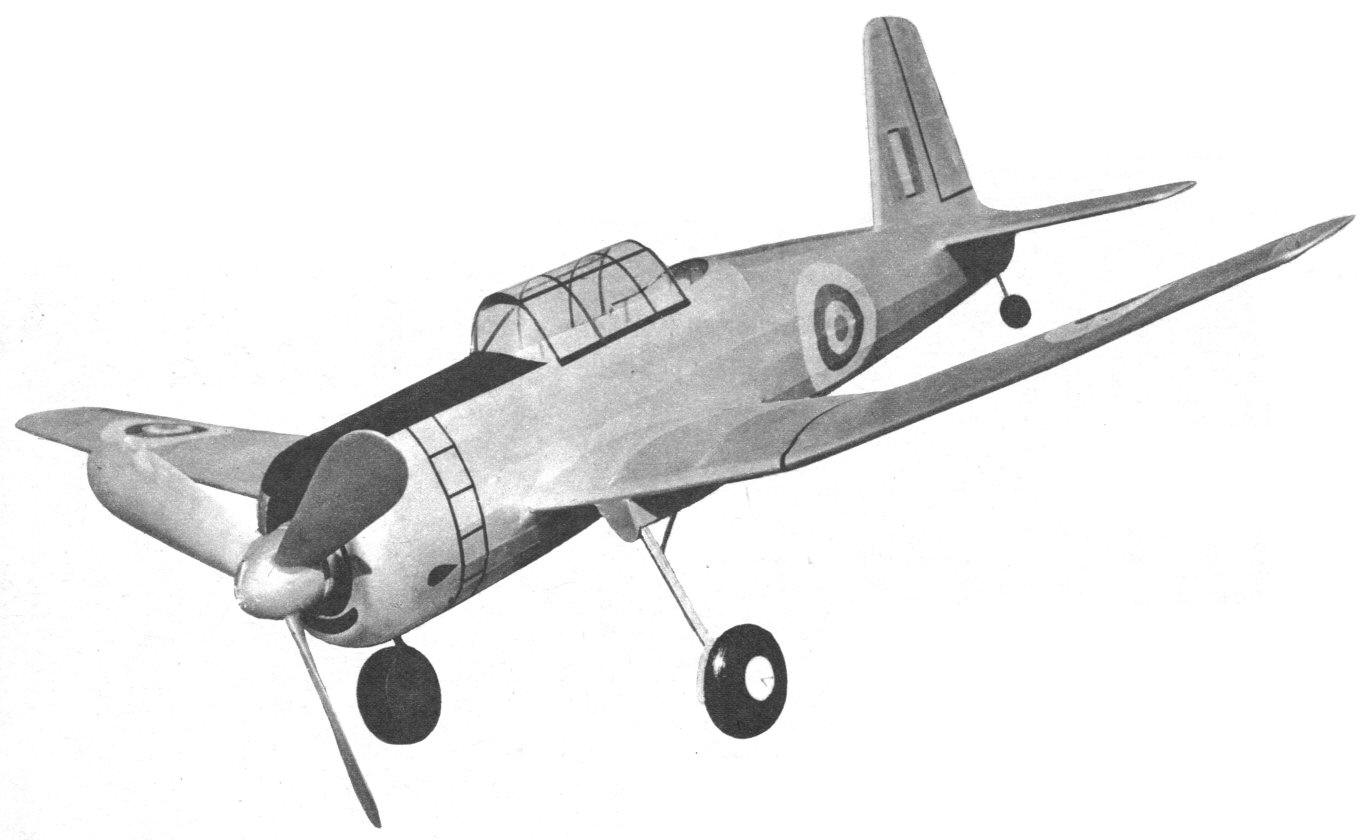
VULTEE VENGEANCE
BY SYDNEY STRUHL This giant flying scale model has real endurance.
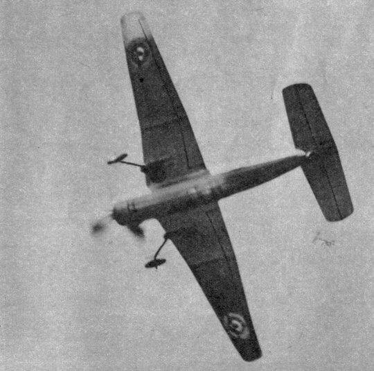
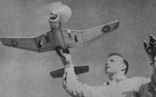
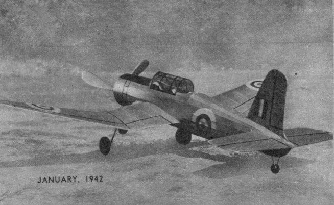
SEARCHING for an airplane that could match the performance of the German Stuka, England cast her eyes toward American manufacturers to see what they had to offer. And in answer to John Bull's problem, Vultee comes crashing through with its latest creation -- the Vengeance. The Vultee Vengeance is a two-place dive bomber of the most striking design. Perhaps the most unusual item in that design is the wing. The odd-shaped wing was created especially for slowing the ship in a vertical dive to obtain the maxium accuracy with the bomb load. The bomb is carried inside the fuselage and is swung into position for release by a special arm. Of course, much of the performance figures of the Vengeance are still a much-guarded secret. We do know, however, that power is supplied by a 1,700 horsepower Wright Cyclone engine, the range is 1,000 miles, service ceiling is 27,000 feet, and the climb is 2,900 feet a minute for the first five minutes. Due to the wing design, the diving speed is less than the maximum horizontal velocity. As a flying-scale model, the Vultee Vengeance is a pippin. Flights are rather fast but exceedingly stable. Flights of two minutes were very common in still evening air. The glide is really something to behold, and when the ship comes floating in for a landing -- well, it sure looks like the real thing. The construction is not too difficult, and if the plans are studied carefully beforehand, you should find no trouble in completing your Vengeance. CONSTRUCTION Use the half-shell construction method for making the fuselage. This is the best system for a fuselage of this type, since there are so many straight lines in the fuselage. Cut the fuselage bulkheads to the exact shape as shown on the plans. Now pin the top and bottom 1/16 x 1/8" center stringers in place, then the bulkhead halves on the plans in their proper locations. Now add the remaining fuselage stringers. These are all 1/16 x 1/8" strips of balsa. Put two coats of cement on each joint and be sure that the cement has set firmly before you remove the frame from the plans. Note that bulkhead K is made from three pieces of 1/16" sheet glued cross-grain. This strength is needed to hold the rear hook. Bend the rear hook from .049 music wire and cement very firmly in K. Cement the remaining fuselage halves to their corresponding members, allow to dry and then add the rest of the fuselage stringers. Cut the cockpit from 1/16" sheet and cement in place. Add the 1/16" sheet fill-in around the wing joint and the soft 1/8" sheet fill-in to simulate the cowling. Shape the tail block from a very soft block of balsa and cement in place. Add the tail wheel of balsa. The tail surfaces are rather simple to construct and are made directly on the plans, the various member sizes being obtained from the plans. Pin the stock in place on the plans and cement the joints firmly. Cut the tips from soft 1/8" sheet balsa. Note that the root rib of the rudder is 1/8 x 1/4". Sand the leading edge and wing tip carefully to form an airfoil section. The trailing edge may be trimmed with a razor and then sanded. Cover the tail surfaces with tissue or Silkspan, as you prefer. Spray with water, allow to dry and then brush on two coats of thin clear dope. Two very thin coats of color dope may be added if you wish. The author used thin silver dope to color his model, but "sand and spinach" camouflage is very appropriate. Like the tail surfaces, the wing is simple to construct and may be made directly on the plans. Cut two ribs from 1/16" sheet of each rib shown in the plans. Pin the 5/32 x 1/2" trailing edge and the center spar in place on the plans. Place the ribs in their proper locations and cement them to the center spar and the trailing edge. The leading edge must be cut from sheet balsa because it is tapered. The leading edge is cut from 1/4" medium-grade sheet balsa. It is 7/16" high at the center section and tapers to 1/4 x 1/4" at the tip. Pin the leading edge in place, blocking it up as required and cement it to the ribs. Now cut the wing tips from 1/8" soft sheet balsa as shown in the plans and glue in place. Carefully sandpaper the leading, trailing edge and wing tip to conform to the general airfoil shape. Cut halfway through the wing spars and crack the joints so that you have 2-1/2" dihedral at each wing tip. Cut four wing gussets from hard 1/16" sheet balsa and cement one on each side of the wing spar to brace the dihedral joint. The wing is not covered until the landing gear is installed. Study the drawings of the landing gear very carefully before you attempt to make it. You will note that each landing-gear leg is composed of two pieces of .049 music wire and a cover piece of 1/16" sheet balsa. Bend the wire struts to the required shape and cement the strut to the back of the leading edge and the bracing strut to the wing spar. Use at least five coats of cement on these joints, and they may even be bound with silk thread. Now bind the two struts together, running the thread all the way down the strut and applying several coats of cement. Cement the landing-gear cover plate on the inside of each strut. Construct the small box formation to fit the bottom of the wing. The two sides are cut from 1/16" sheet and cemented right on the paper. The leading-edge portion is cut from a soft balsa block and is cemented on the leading edge of the wing directly in front of the landing-gear strut. Cut the 2-1/4" diameter wheels from soft balsa. Several sheets of balsa may be glued together to obtain the required thickness of the wheels. You will notice that you will only be able to install the landing-gear strut after the wing is slipped through the fuselage. A drop of cement at the end of each axle will keep the wheels in place. The fuselage may now be covered. It is advisable to use wet Silkspan in covering the fuselage because of the ease afforded in covering compound curves. Treat the covering in the usual manner. Cover the cockpits with heavy celluloid. The tail surfaces may now be cemented in place. A three-bladed propeller was used to keep the scale and to keep the landing gear down to scale size. If you aren't hep to carving a propeller, you may purchase two 12-1/2" machine-cut props, cut them in half at the hub and thus obtain three finished prop blades with one blade to spare. However, a more efficient propeller will result if you carve the prop yourself. Obtain three blocks 1-1/4 x 1-3/4 x 6-1/4" and lay them out as shown in the sketch in the plans. Pin each to the bench and assemble as shown before carving. Strengthen the hub by carving and installing the large prop spinner. Carve the prop in the usual manner, rounding the tips after this operation has been completed. To balance the three-bladed propeller, point one blade directly down. Lighten the one that descends to balance the third blade. The blade that was originally pointed down, and this should be the heaviest to facilitate the task, is then balanced in a similar manner against one of the other blades. Although a freewheeling device is not required, its use is advisable to obtain longer flights. Make the nose plug from two disks of 3/8" sheet balsa glued cross-grain. Now cut a small square of balsa to fit snugly in bulkhead B and cement it to the back of the nose plug. Cement large-faced bushings to the back of the prop spinner, to the face of the nose plug, and a washer to the back of the plug. The prop shaft is bent from .049 music wire. Use a ball-bearing washer between the propeller and the nose plug. The power is supplied by eight to ten strands of 3/16" flat brown contest rubber, depending on the weight of the finished model. The rubber is worked onto the rear hook by the use of a long wire hook manipulated through the front of the model. FLYING If possible, test your Vengeance over grass to prevent damage during this stage. Otherwise, test your model R.O.G. on a few turns, increasing the winds as the balance is ascertained. If you have followed the plans carefully you will need very little adjusting to make your ship behave. A small weight may be used to balance it if necessary. Do not warp the tail surfaces, as they tend to change their setting from time to time. The original. model needed only an adjustment of offsetting the prop to the right a bit to obtain a circle against torque in flight. When you lube up the motor, stretch it out and start winding with a strong winder. Then look out, for when you launch the ship you're going to think you just sent off a Wakefield model, the way it gets, up in the blue and- stays there!
Scanned From January 1942
|
||||||||||||||||||||||||||||||||||||||||||||||||||||||||||||||||