|
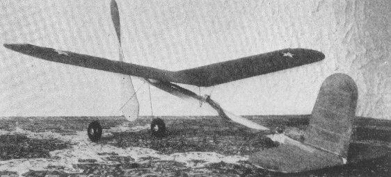
A Stall-Proof How You Can Build a High Efficiency Experimental Flier By RALEIGH T. DANIEL
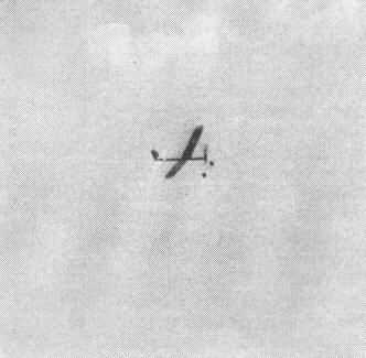
THIS model was designed with a view to producing an airplane for consistently well balanced and dependable flying. As to hard usage, if reasonably well built and adjusted, it can be flown indefinitely without crack-ups or major repairs. The action photo of this ship will illustrate some of its flying ability. Those white clouds which appear in the picture are high above the Rockies. The model itself was launched at an elevation of more than 6,000 feet above sea level. However, the prevailing condition of dry air in this area helps compensate for the thin atmosphere. In the description and instructions that follow, considerable attention is given to detail so that beginners will not have undue difficulty.
Construction Wing First draw a full sized outline of the wing. Also draw lines representing the position of each rib. Attach your drawing to a smooth board or even surface table top. Now make a copy of the rib to use for a pattern. Cut 19 ribs from 1/32 sheet balsa making each one just a little oversized. Stack them together evenly and force pins through from each side to hold them together. The entire group of ribs is then sanded to agree in shape with the pattern. Use sandpaper wrapped around a rectangular block. Make a final check of rib shape by the original drawing. Select straight balsa strips for the spars. Cut them to length and secure in place on the drawing using pins or thumb-tacks or both. Put the ribs in place. It will be necessary to slip a strip of material under the front spar in order to raise it high enough to butt the ribs properly. Cement the ribs and spars securely together, omitting the center rib until later. Use several applications of cement. The tips are made preferably of bamboo but if you have difficulty in working it, then use 1/16 sheet balsa as shown. The principal advantage of bamboo lies in its toughness and will protect the wing in cases where balsa would not. If sheet balsa is used for a tip, stiffen it up with a straight bamboo strip as shown. Do not disturb the wing until the cement is thoroughly dry. The spars can then be sanded to shape. Cut partly through each spar at the center, underside and crack them to raise each tip 2-3/16". Hold them in this position by placing weights on top at the center and near each tip. Slide blocks under the tips in such a manner as to raise them the correct amount. The wing center section is reinforced by use of pieces "H. H" cut from 1/16" sheet. These are attached as shown in detail "A". Now is the time to see that the wing is true and to check and adjust it. It is very important that neither half be warped. When the cement has dried well, the wing may be taken tip and the parts "H" trimmed down until they coincide in shape with the spars. The center ribs should he put in now and also the 1/16 x 1/16" spar. Make four wing cleats from 1/32" sheet dural or aluminum. Attach these in place on the spars using thread and cement. The wing is now ready to he covered. Cut the tissue oversize and trim off later. Tissue cement is preferred for sticking the tissue on. Apply it to the wood with a small brush. Cover the bottom from the center rib to the tip with a single piece of tissue and likewise the top. Thus four separate pieces are required to cover the entire surface. However, a smoother job can be obtained by taking a section from the center to the outermost rib and using another piece over the tip. In the latter case the wing is divided into eight cover sections. The finished wing may be lightly sprayed with water to tighten the covering. Use moderately. Later on it is advisable to dope the paper as it is thereby toughened and made more nearly air-tight. If used wisely, the dope will not produce excessive weight. The trouble at the bottom of many poor cover jobs lies in the fact that the builder tries to cover too large an area with a single piece of tissue. This is especially true where the shape of the framework changes abruptly or where there are compound curves. Tail Structure Make a full size drawing of the fin and stabilizer and follow a similar procedure with the tail frames as described for the wing. The ribs should give little difficulty since they are not curved, necessarily. However, the ribs may he given streamlined shape if desired and they are thus made a little more efficient. It is recommended that the beginner use the simpler ribs as shown. For typical rib shapes see sections B-B and C-C. Make ribs of 1/32" sheet balsa, medium weight. The stabilizer and fin tips are cut from 1/16" sheet balsa, fairly soft. Sanding the spars should be the last operation before covering the structure. Cover the fin with tissue on both sides. Cover the stabilizer on top only unless curved ribs are used. The tail booms are cemented on top of the stabilizer. Trim off a small space of tissue in four places on top of the stabilizer spars where the tail boons are to rest. This is to make a firm joint, for were the parts merely cemented onto the paper they would pull off. The fin is attached on top of the stabilizer and between the 1/16 x 1/4" booms. For installation see detail "k". Miscellaneous Make the tail skid and wing clips from music wire. Make a full size landing gear outline on paper and bend the wire to match. Make a motor guide from 1/32" sheet dural or plain aluminum. Form the circular part by bending around a rod or the like. Secure about midway under the wing onto the motor stick, using thread only. Use a propeller shaft as a rear motor hook. Push it through the motor stick from the top near the rear end and bend at 90 degrees rearwardly and cut off. Cement it and bind with No. 50 thread. Attach the tail skid also with thread and cement. Cement a 3/16 O.D. washer on each side of each wheel hub. Line the washers up by passing a pin through them and the wheel hub. For the sake of a good finish and fine appearance, smooth off the wheel surface with fine grit sandpaper and apply several coats of black dope. The wheels are then put on the axles and the music wire is bent rearwardly and cut off. Put the landing gear on the motor stick and secure with generous applications of cement and thread. True it up before the cement dries. Use a 9" diameter propeller having a pitch of about 14-1/2". This may be cut from a block 7/8 x 1-3/4 x 9". If inexperienced in carving props, it may be advisable to use one that is machine made. To finish the latter you need only to round off the tips with a razor blade and give final shape with sandpaper. A simple bearing set-up is shown in detail "M," which consists of 3 washers, 1 "L" type thrust bearing and a shaft on which is mounted the propeller. It will probably be necessary for best performance that the prop be set for a slight down thrust. That is, the rear end of the shaft is raised slightly. This raises the point through which the thrust line passes under the wing. When so adjusted it will be found that the model has an excellent climb in combination with a flat glide. If your model has a tendency to stall while in power flight when it is at the same time adjusted for the best possible glide, it is recommended that you adjust the thrust line as mentioned, a little at a time until the best results are attained. This function was attained on the original model with the use of a Travis Multi-Flex Bearing with Free Wheeling Clutch. About 6 or 8 strands (3 or 4 complete loops) of 1/8x 1/30 brown rubber is necessary for the motor. Allow a couple of inches slack in the rubber. Mount the wing on the motor stick in about the position as shown. The tail structure or empennage is secured to the motor stick by means of white cotton twine not thread. Wrap the twine very tightly. This will allow adjustment of the stabilizer angular setting and at the same time prevent jarring loose of the adjustment while in use, if wound tightly. When all details have been done, adjust the wing position forward or rearwardly until the model balances just ahead of the center of the wing. Now try for a glide. Set the stabilizer up or down until the flattest and most even sort of glide is obtained, at which time the model is ready to be wound up for power flights. Scanned From February 1938
|