|
Building The "Tyro I"-Outdoor Glider
A Simple But Efficient Plane That Anyone May Build in a Short Time at a Cost of a Few Cents By BRUNO P. MARCHI
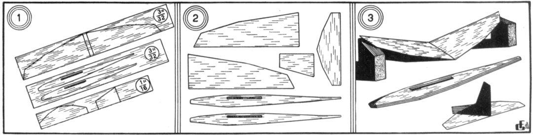
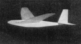
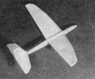
"OH, IT zips through the air with the greatest of speed . . ." Speaking, of course, of the "Tyro I"; which embodies many features found only in high performance contest types, yet a glider which can be made in a very short time. Glance at the plans and note the simple, rugged construction and the many shortcuts to quicker completion. It is the author's contention that any beginning modeler can build this craft. To prove his point, plans of the "Tyro I" were given to a representative group of inexperienced fliers and all produced fine flying gliders. Although following the accepted lines for advanced contest entries, the "Tyro I" is easy to build because of its flat wings, straight edges on wing and tail surfaces and its unique wing setting arrangement. Required to build this model are approximately eight cents worth of sheet balsa and glue in addition to carbon paper, cardboard, sandpaper, modeling clay, single edge razor blade, pencil and ruler. Yet when finished, ready to perform with its proper nose weight of modeling clay. this glider is big enough and heavy enough to enter either an N.A.A. sanctioned outdoor event for Class B hand-launched gliders or any official outdoor glider meet. Construction First read this brief article carefully. Then secure some cardboard of the same thickness found in suit boxes, and, using carbon paper, trace the fuselage side, wing and tail surfaces on the cardboard. Next step is to carefully cut out the cardboard copies of these parts which will then become templates. Make two outlines of the wing panel and fuselage side on 3/32" inch, medium hard, three inches wide sheet balsa. Outline the stabilizer and rudder on 1/16" medium hard, two inches wide sheet balsa. These steps are illustrated in diagram No. 1. With a single edge razor blade (to save shredding the fingers), cut out the glider's parts as shown in diagram No. 2, using care when cutting out the wing slots in the two fuselage sides. Final step in preparing the various parts for assembly is beveling each wing panel where they are to be joined at the angle shown in enlarged "Section A-C" on the plan. Thus, when both wings have a dihedral angle of two inches their centers fit together snugly. Sandpaper the sharp edges of the wing and tail surfaces to produce rounded leading and trailing edges and tips. Here is where we let you in on a secret : "Precoat all joints to make 'em stronger, And gliders stay together longer." Precoating means applying cement to sections which will later be glued together. This operation provides a foundation for the final joining, by filling up the pores in the wood. So give a preliminary coating of cement to the wing centers, the sides of the fuselages where they are to be joined together, the stabilizer slot on each fuselage side, the bottom of the rudder and the top of the stabilizer. These areas are all shown on the plan. After permitting a second precoating of cement to dry thoroughly, the wing panels are joined with two inches of dihedral on each side as shown, or four inches on one panel when the other panel is flat on the work board. Glue the fuselage sides together and cement the rudder on top of the stabilizer, making certain the rudder After the wing panels are glued together, apply this coating of cement along the top and bottom of the joint. Do this several times, spreading a thin skin or coating of glue along both sides of each panel with a finger or glue stick covering the area indicated on the drawing. The final assembly task is to slip the wing through the fuselage slot with the straight edge to the rear, so as to form the trailing edge. Should it be necessary to enlarge the wing slot slightly, don't make the opening so large that the wing will fit too loosely. Glue the stabilizer and rudder tail group in place in the fuselage slot. With the rudder in line with the fuselage, slide the wing into a position of equal dihedral for each panel in relation to the stabilizer, by sighting from the front or rear of the glider. Then the wing and stabilizer may be cemented to the fuselage and several successive after-coats of glue applied at these points. This will strengthen the joints, and fair or streamline the wing and stabilizer to the fuselage. Adjustment Adjust the glider in an open field by adding weight in the form of modeling clay to the nose until the craft glides smoothly. It will be found that when this point is reached, the glider will balance about one and a half inches forward of the trailing edge. This point of balance will vary according to the weight of the wood used in the construction. Bend the trailing edge of the rudder to the left for a left circle, and to the right for a right circle. Grasping the glider by the fuselage with the thumb and first two fingers just below and in front of the wing's trailing edge, point the model's nose upwards slightly and launch with a "heave." Should the model show a tendency to go into a spiral dive, correct by bending down the trailing edge of the wing on whichever side the model turns. By carefully bending the various tail units, the builder will be able to see the effects this will have on the glider's flight and can learn for himself the principles of correct adjustment when coupled with good design. After recording the best flights, moisten the top side of each wing panel slightly with water, permitting each to dry naturally. It will be found that this produces a semi-airfoil shape on both panels which may be decreased or increased by breathing on the wing and bending the balsa wood with the fingers. Immediate benefits from this airfoil should be apparent in increased duration and smoother flights. Thus, by building and flying the "Tyro I" you have learned by actual experimentation the value of an airfoil section on the lifting surfaces of an airplane, the precoating technique and the ease of working with templates. Scanned From June, 1938
|