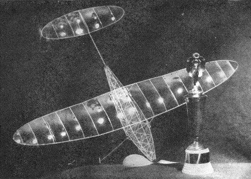
The "Indoor Cabin" Nationals Winner
THE CABIN model has been a feature of indoor meets for years but it still attracts scarcely half the number of entrants found in the stick event. As the possessor of a good "cabin" stands a much better chance of making a winning flight, it must be the fragile and complex appearance of this type of ship that keeps the entry list so small. Most of those that are built reflect this impression by a much heavier and stronger construction than necessary, in direct violation of the indoor builder's creed : "Sand it down to nothing-then cut it in half!" We believe that a cabin can be made as light as a
"stick," and still prove itself a stronger model, a more consistent flyer,
and capable of nearly as great duration. A built-up fuselage of large
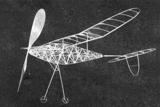
cross section can resist bending and twisting better than a stick, yet
need be no heavier than by the weight of the landing gear. By the use of
four struts spaced some distance apart the wing may be mounted more
rigidly and built lighter The points discussed seem to be borne out by the performance of this model to date. At the 1938 National Meet this ship established a new Open Class record with a flight of 16', 01"; the best cabin time of the day by more than two minutes. Later flown in a New York armory it set a local mark of 12', 15" under a sixty foot ceiling. Material Very little material is needed to build an indoor model, but only the best grade of light, firm balsa, generally referred to as "indoor wood" should be used.
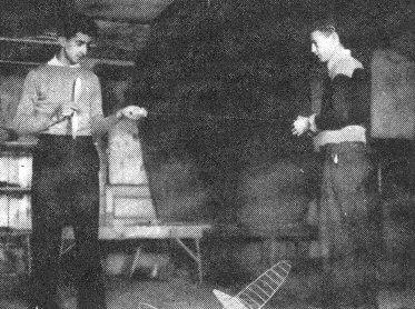
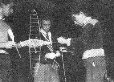
Fuselage Plate I is drawn 1/4 actual size and fully dimensioned. Full size templates may be found on Plate II. A table of weights is given on Plate I against which the individual parts can be checked as construction progresses. On a smooth board, or sheet of heavy corrugated cardboard, draw a full size fuselage side layout. Construct two sides of 3/64" square balsa, one atop the other. Cut the uprights in groups of four using the extra pairs to connect the sides. A perfectly symmetrical body is assured in this way. With a razor, guided by a straight edge, cut 1/8" and 1/16" wide strips from superfine tissue. Tack them on the fuselage frame, using dope for adhesive. Use a separate piece for each panel, being careful not to pull it too tight, to avoid warping the fuselage. The wide brace strips in order to be in tension when the rubber is wound must be run from the upper left to the lower right hand corner of each panel. The plugs consist of snug fitting squares of 1/32" x 1/16" balsa cemented to 1/32" sheet faces. Build up a pyramid of 1/64" sheet balsa on the nose plug and cement washers to its apex and the back of the face. (See Nose Plug Detail sketch.) Bend the rear hook of .014 piano wire and cement it in the tail plug. (See Tail Plug Detail sketch.) The tear drop section tail boom is formed on a 1/16" wire, from a sanded down blank of 1/64" sheet balsa, and mounted on the back of the tail plug. The wheel rims are 1/32" square balsa, moistened and bent around a soldering iron or hot tube, 1-1/4" in diameter. Bearings are made of strips of superfine tissue rolled on a pin and slivers of bamboo used for axles. (See Wheel Detail sketch.) The landing gear struts are not attached till the fuselage has been covered with microfilm. Surfaces The wing, tail and rudder are all constructed in identical fashion and so will he described as a group. The surfaces are elliptical in plan and can be easily plotted on the workboard as illustrated on the drawings. Divide the span in eight equal parts, with each tip section divided in half again. Scribe a circle with a radius of one-half the maximum chord and divide its horizontal diameter into a similar number of equal parts. Draw horizontal lines from each intersection on the circle to the corresponding division of the span. Connect these positions with drawing curves to complete the ellipse. Sandpaper a sheet 1/16" x 1-1/8" x 18" balsa, tapering it evenly to a scant 1/32" thick at one end. Cut ten spars, tapering from 3/32" to 1/32" from this sheet. The spars may bend as a unit if the cuts are not made to the very ends of the sheet. Moisten the wood thoroughly and slide it evenly across a soldering iron or piece of heated tubing, regulating the amount of curve by the speed and pressure with which the wood is moved. (See Bending Strips.) Pin the spars to the plans cutting them to the required lengths and join the tips. (See Tip Detail sketch.) Make a rib template from thin metal, tracing the pattern given on Plate II. The ribs are cut from a sheet of 1/32" x 2" x 6" quartergrained balsa, by sliding the template down 1/32" after each cut. Fit the ribs in position, cutting the excess length from their trailing edges. Propeller The grain and texture of the propeller block must be constant if the blades are to be of equal weight and strength. For this reason the block should be laid out in the somewhat unusual manner shown on the plans. Carve the blanks roughly with a sharp knife. Glue the blades together overlapping the joint 1/2", drill the shaft hole and continue carving till a thickness of less than 1/16" has been reached. At this stage be careful to maintain the proper amount of camber. Cut the blades to the pattern given on Plate II and finish them with successively finer grades of sandpaper, finally polishing the surface with ten nought. Cement a washer to the hub and insert the prop shaft of .014 wire including a free washer between the propeller and nose plug. Assembly and Flying The model should not be covered with too thin microfilm as the savings in weight is infinitesimal and the film much more liable to puncture. Sheets running red to green in color are good. Cement the wing clip rails of 3/64" square balsa to the side longerons. The wing struts are attached to the rails by clips bent of .005 sheet aluminum. Be sure the wing is not warped when mounted in place. Wind a loop of 3/32" flat, lubricated, brown rubber just about enough to take out the slack. Pull the motor through the fuselage by a long hook of 1/16" wire and transfer the rubber to the rear hook. (See photographs.) Follow this procedure whenever winding, else the model may be destroyed if the rubber should break. Glide the model, correcting any tendency to stall by moving the wing back, or vice versa for too steep a descent. Test fly the ship with about 600 turns, adjusting it to fly in left circles of 35 to 45 feet. Avoid warping the rubber excessively, aiding the turn if necessary by off-setting the thrust line to the left with a tiny sliver of balsa between the nose plug and the fuselage. This combination was used on the original and seemed to work very efficiently. Gradually increase the number of winds till the maximum altitude available is reached. The amount of climb can be regulated by increasing or decreasing the length of the rubber loop or "slack." If flying conditions are poor 7/64" flat rubber with plenty of slack will prove more efficient than thinner rubber with less slack. In any event this cabin is capable of turning in high enough durations to put a kink in the neck of any modeler if he must watch his ship dodging in and out of the rafters. Scanned From July, 1939
|
|||||||||||||||||||||||||||||||||