|
Building A Baby Biplane A Simple Plane That Will Provide Worlds of Fun and By ROBERT C. HARE
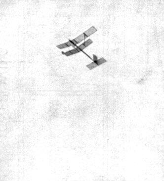
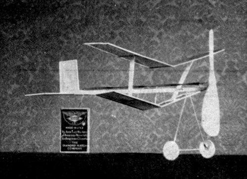
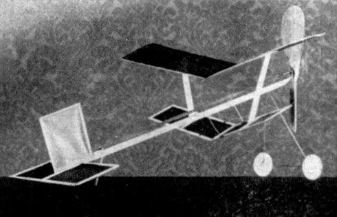
EVERY model builder has, one or more times in his career, felt a strong desire to construct a biplane of a given type which would perform as well as any monoplane in the same category. However few young men have achieved this goal, for model biplanes are tricky craft and what may appear to be "the" ship on paper more often than not fails to fly at all. Biplane R-8 described here will be welcomed by novice builders possessing a "biplane complex" while experienced builders will find many hours of first-class flights available to them during production of other types. It was during the latter case that the R-8 was conceived by the writer. This little biplane was built with the goal in mind to surpass in every way the performance of a conventional monoplane ROG used in coaching beginners. All of which takes in a lot of territory when one considers that in a biplane we find two centers of aerodynamic force in the cellule which must balance to insure normal flight. In addition to providing enough lift to support the machine in the air, the resultant force of the R-8 had to be sufficiently great to overcome the considerable structural drag common to this type of machine. Construction Begin the R-8 by constructing the fuselage and its components. Select a piece of medium weight balsa 8 inches long with a 5/32 x 3/32 inch cross section, sand it smooth and curve one end as shown in the drawing. This will be the lower side and the front as well. Notch the rear end at the bottom by cutting out a piece 1/16 x 1/4 inches and into this channel fit the 1/16 inch square balsa extension. Its length is 2 inches. Next make the thrust hearing from a piece of thin aluminum, tin, or brass and drill a small shaft hole near one end. Bend the sheet to the shape shown in the plans so that the hole will allow a clearance of 3/32 inch between the shaft and the motor stick. Cement the hearing securely in its proper place; binding with thread is not necessary. At the rear end of the stick, cement a rear hook securely in place after the short prong has been stink into the wood to add strength. The tail skid is made of split bamboo 1/32 inch in diameter cut to the length shown in the plans. Sharpen one end and jab the skid into the motor stick a distance of about 3/32 inch and cement the joint well. When this has dried the two landing gear struts may be made and attached. Each strut is cut to length from 1/32 inch diameter bamboo. Sharpen one end of each strut and with a pin make two small holes about 3/32 inch deep at each lower corner of the stick. These holes should be 1-1/8 inches from the front and on such an angle as to provide a tread of 2-1/2 inches. Cement these joints thoroughly but be sure to true and align the legs before the cement hardens. In building the two axel bearings, the novice will find a sample of finer model work. These bearings are made of thin aluminum sheet cut to the outline shown in axel drawing "B." The hole should be 3/64 inch in diameter. To attach these bearings set them on the outsides of the landing gear struts and bend their upper sides around the struts as shown in "BB." This can he accomplished with the aid of fine nose pliers. The preliminary fit need only be tight enough to prevent the bearings' coming off. This operation completed, securely cement these bearings to the struts, taking care to see that they are aligned correctly. While the above is drying, cut two 3/4 inch diameter wheels from 1/16 inch sheet balsa stock and with a pin drill a tiny hole in the center of each. The axel is then cut to length from 1/32 inch diameter bamboo. To assemble, slip one wheel on the axel so that about 1/32 inch of the axel projects from the hub. A drop of cement will hold the wheel in place. Then slide the axel through both bearings and slip the other wheel over the protruding end and cut so that about 1/32 inch of the axel projects beyond the wheel. A drop of cement here will securely fasten the wheel and will provide a smooth running gear of the rotating axel type. Rudder and elevator units are built up from 1/32 by 1/16 inch balsa strips, shapes of which are shown in the plans. Notice that the elevator ribs have a decided reversed camber section. This section, although not employed in the original R-8, will greatly reduce the tendency to stall in this or any similar type ship. Notice that the rudder has only three members which, when assembled, is cemented with open ends resting on the outrigger extension as shown in the drawings. When dry, cover the rudder on one side only, preferably on the left. When the elevator-stabilizer frame is dry and covered (on the bottom side only) cement it in place as indicated. This member is set at zero degrees angle of incidence. Be careful that its leading edges form a 90 degree angle to the motor stick on either side. The unit which makes the R-8 the fine flyer it is, the biplane cellule, may be constructed next. For the upper wing slice two spars 5/32 inch wide from 1/32 inch sheet balsa stock. Cut each strip to its proper length and crack in the exact center to provide the proper amount of dihedral shown in the plans. Make sure as well, that the proper amount of wash-out is incorporated in the left half of the panel, as shown in the drawings. Five ribs of the same stock are bent to the curve shown in the side-view drawing. This curve may be obtained by rolling the ribs with a pencil, or by steaming a one-inch piece of the proper size material cut to chord length. A uniform set of ribs may then be slit off with a sharp razor point. Proceed in the same manner with the lower wing. Note however that lower wing spars and ribs are all 1/32 x 3/32 inch balsa and that the section is absolutely flat. There is no wash-out in this plane. Two points to which particular attention should be paid in wing construction are: First, be sure that ribs and spars are in perfect alignment, and second, that the cracked center of each spar is well coated with a skin of glue for strength. Wing-clips are fitted to the lower plane only. Bend these fittings from No. 8 music wire to the shape illustrated. The lower extremities of each leg should be bent to form circular "feet" which will provide sufficient surface for permanent attachment to the wing spars. In covering the upper wing, paper one side at a time in order to prevent uneven surfacing near the center rib. The upper wing is covered on the top side only and the lower wing on the bottom. While clips are drying, select a piece of light balsa for the propeller, dimensions of which are given in the plans. Shaded areas indicate those parts of the block which are removed to form the working blank. Once the blank is obtained, drill the shaft hole using a bank pin as a tool. Be sure the hole is in perfect alignment to insure against a wobbly prop. From there on the blades are carved and sanded as usual to a thickness of approximately 1/32 inch. When the propeller is balanced, and take pains that it is, insert the No. 8 music wire shaft, bent as shown in the plans, and press the front prong firmly into the hub. Cement securely. The bearing consists of a small brass or aluminum washer next to the propeller, and a small glass bead selected for its uniformity. Beads of this type may be purchased at the ten-cent store in your neighborhood where they are sold for ornamental bead work. A bottle or packet of several hundred will cost not more than a dime. Now we return to the wings and prepare to "rig" up the R-8. First step is to attach the lower wing, by means of the clips, in the position shown in the plans, and to jack up the tail until the fuselage is in a perfectly horizontal position. Referring to the plans, cut two interplane struts to the size shown. Be sure to get the bottom and top shapes absolutely correct as the stagger depends upon this. When the struts are matched and found to be perfectly identical in every way, mark lightly with soft pencil on the intermediate ribs a point 3/8 inch back from the leading edge. Do this on both planes. When this operation is completed apply cement liberally to the lower (flat) end of each strut and set its leading edge on the previously made pencilmark. Hold the struts in a vertical position until the cement has set lightly (until they will remain erect unsupported). Then quickly apply cement to the upper strut ends and adjust their vertical angles so their leading edges will set on the upper rib marks. If cutting has been accurate you will now have a biplane cellule of great strength and efficiency with the following characteristics: Incidence, upper wings zero degrees, lower wings 6 degrees. Stagger will be 3/4 inch and area 21-3/16 square inches. The conventional monoplane R.O.G. of the same size has an area of about 24 square inches. Before the cement sets permanently, sight the R-8 from front and top to make sure that the middle upper plane rib is exactly superimposed over the fuselage. The R-8 should now be allowed to rest in its horizontal position for at least 1/2 hour once the cellule has been made true. By now you will notice that the R-8 is quite a snappy-looking machine in contrast with the side-view drawing printed here, which for sake of simplicity was drawn without showing dihedral. The propeller may be hooked to the hanger and a motor of one strand 1/8 inch flat rubber with 1/2 inch of sag put on. Two ways of applying the motor depend entirely upon the performance desired. For hand-wound flights the rubber may be punctured about 1/8 inch from each end by pressing it on the sharp points of the shaft hook and rear hook. For long flights where a winder is used to store up energy, simply tie a loop in each end of the motor and rig without slack but using an "S" hook. The builder found the former method entirely satisfactory for outdoor flights of about a minute where the motor was handwound. As many as 275 turns may be stored up in this manner provided fresh rubber of a good grade is used. With a winder, 800 turns applied to the R-8, when flown outdoors, will provided flights upwards of 3 minutes in duration; the model at times climbing so high as to become an exceedingly small object on which to focus one's eyes. Before actual flight balance the model by shifting its wings until a smooth long glide is obtained. For the first flight give the motor 150 turns and set the R-8 on the ground, outdoors provided the air is still. If adjustments are correct the R-8 will leap from the ground and assume an extremely steep climbing angle attaining an altitude of 20 feet or more before coming to earth "dead stick." When you have found finer adjustments, give the R-8 its full complement of turns and sit back to watch some first-class flying. She will leap from the ground and begin a vertical climb, roll, fly level, then stick her nose up in an angle at which any monoplane R.O.G. would stall ! The author would advise, however, that flights performed with a fully-wound motor be carried out in a large open space, imperatively so if a winder is used. With two strands of 1/8 inch flat rubber the R-8 will rocket around the sky in a series of loops, rolls and steep zooms that make pursuit aviation look like motorless gliding. Performance over a wide range of power applications? Yes! The answer is simply that the R-8 possesses aerodynamic efficiency combined with lightness and strength, proven through more than 200 separate flights indoors and out, nearly three hours in the air made by the original machine. Scanned From December, 1939
|