|
Build this little A miniature engine in a little ship . . . But the
combination by David D. Grant
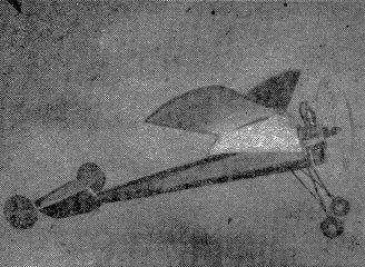
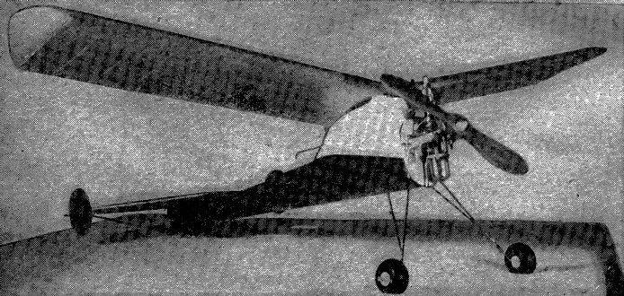
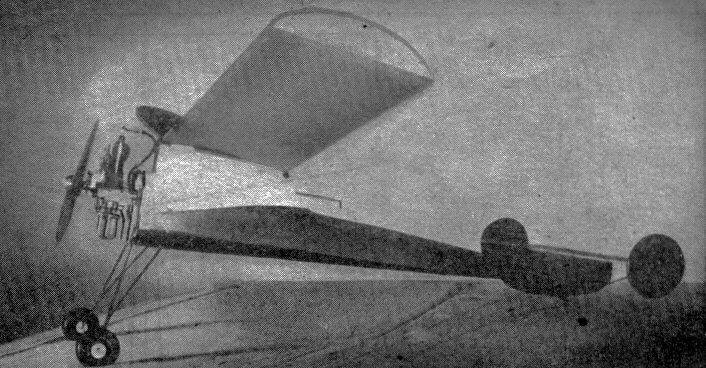
THERE'S NOTHING effeminate about this model plane, just because it bears the name of a Mexican pooch that's a favorite with the ladies. The Chihuahua (pronounced she-wah-wah) is the smallest dog in the world, never weighing over five pounds and which can stand comfortably in the palm of your hand. But after watching this "pooch" flyer go to town, you'll agree that it might be quite necessary to put a leash on it. For when she starts puttin' on the dog, she's doggone good. And while this vestpocket edition gas job doesn't weigh anywhere near five pounds, it can be handled with the greatest of ease. Our flyin' "pooch" is powered with an Atom engine and is exceptionally stable for a ship its size and proportions. After collecting the necessary lumber specified in the material list, lay a large sheet of wrapping paper on the workbench onto which the fuselage side is to be drawn. FUSELAGE CONSTRUCTION DRAW FULL SIZE layouts of the fuselage frames, wings, and stabilizer. This is easy, because all are straight lines and just twice the size of the drawings appearing on the following pages. Make two side frames of 1/8" square balsa and join them with cross braces of the same material. While these dry, lay out the landing gear drawing, by scaling it up from the assembly view. Note that the front wire goes across the upper front cross brace, down the front side pieces, and then out and forward to the bend for the axle. The rear wire runs across the bottom brace, then out and forward to the front wire, where it is bent to run along the front wire for a half inch. Both legs bent from 1/16" music wire. When the landing gear legs have been shaped glue them to the fuselage and lash them down firmly with strong thread. Also, take six or seven turns of the same thread between the legs of the front wire across the bottom cross brace, to prevent landing shocks from splitting the fuselage apart. All lashing should be coated with cement. Next make the bulkheads, which are shown full size on the drawing. Nos. B-1, B-2-U, and B-3-U are cut from 1/8" medium hard sheet balsa. Upper and lower bulkheads are identical except at stations 2 and 3. The rest are 1/16" flat balsa, except B-7, which is also 1/8" thick. Set them in place on the fuselage frame, and glue firmly. From 1/16" flat, cut two floor pieces for the wing mount; one fitted across the top of the frame between B-1 and B-2-U, the other between B-3-U and B-4. These are shown in the side view layout by dotted lines. Glue them in firmly, and then cut the vertical braces, R and S, as shown in the side view. These are set on the centerlines. Add the wing mount trailing edges, which is tapered to a knife edge from 1/16" by 1/8" balsa. Lay out the pattern of the wing mount top, and cut a right and left half from 1/16" flat balsa. Mark the outline of the timer. Glue the top in place on the frame, and cover the mount with 1/32" flat balsa. Sand slightly thinner so as to bend easily. The grain runs vertically around the sharp bend in front, and horizontally from B-2-U back. Next, cut two outlines of the side frames from 1/16" flat balsa, and cement them to the sides. Cover the top and bottom of the fuselage with 1/32" balsa, as far back as the curved line between stations 4 and 5 on top, and between 3 and 4 on the bottom. Run a 1/16" square stringer down the center line from the balsa cover to bulkhead 7. Do not notch any of the bulkheads for the stringers; just glue them to the tops of the bulkheads, except B-7 which should be already notched. Add two more stringers to the top and bottom in the same manner, terminating them on the top longeron about 1" forward of B-7. Cut out the outline of the timer from the top of the motor mount. Solder two lengths of ignition wire to a pair of long bushings for use as jacks, and thread the wires through the holes in B-1 and B-2-U. Cement the bushings into B-1. Connect the ends of the wires to the timer terminals, and set the timer for twenty seconds. Attach a piece of wire or strong cord to the handle of the timer. Cut away notch X in the trailing edge of the wing mount, run the timer wire or cord through it, and fit the timer into the wing mount. It is held firmly in place by wedges of soft balsa, which are likely glued in place. Be careful in fitting the wedges so as not to interfere with the contact strip of the timer. TAIL SURFACES BUILD UP THE fin directly on the tail of the fuselage. F-1 is cut to shape from medium hard 1/8" flat balsa. Its bottom edge is sanded round. The tail post, F-3, also 1/8" flat, is next. Make the leading edge from 1/8" by 1/4", and fit it in place at B-7. The lower rib is a strip of 1/16" by 1/8" fitted between the leading edge and the tail post, flat on the top of the fuselage. Cut two side covers from soft 1/8" flat, and sand to a streamline shape as shown in the top view before cementing them in place. The top rib, made from 1/16" flat balsa, runs the full length of the assembly, and is added next. F-2 is cut as a single unit from medium 1/8" flat and streamliner. The tab is cut out last. Hinge the tab by a pair of pins or wires as shown by the dotted lines and make sure it is tight enough to stay in any position in which it is set. Cut F-4 from the same 1/8" stock, and round the bottom edge. The remaining rib is 1/16" flat. The stabilizer is built directly on the layout drawing. The main spar is 1/8" by 1/4" and the leading edge 1/8" square. The trailing edge is 1/16" by 1/4" tapered to a sharp edge. The ribs are all 1/16" by 1/4", sanded to correct contour after assembly with the exception of the center rib, which is 1/8" thick. Add a strip of 1/8" square along each side of the center rib, flush with the bottom, and cement firmly. The twin rudders are shaper from balsa plywood, mare up of three sheets of 1/32" medium soft stock glued together with the grain at right angles. The rudders are circular in plan, and streamlined. The firewall is cut from three ply birch 1/16" thick. To the firewall, cement the sides and bottom of the power unit box. These are cut from 1/16" flat medium hard balsa, and fitted to the inside of the fuselage frame before adding the firewall. The fit should be tight enough so that there is no play in the box. Not too tight, however, that it cannot be easily slid out. The front edges should be sanded so that the firewall will stand parallel to the front of the fuselage frame. Reenforce with 1/8" square cemented inside the joints at sides and bottom of the tray where it joins the firewall. Add a 1/8" square piece across the bottom to prevent the coil from slipping back in the tray. MOTOR MOUNT CUT THE MOTOR bearers from either 3/16" by 5/16" spruce, poplar, or white pine. Taper them as shown in the top view, and cement firmly in place. They are to be exactly 1" apart, parallel, and square with the fireball. Add a pair of dural angles underneath the bearers as shown in the side view. Bolt holes are drilled through the bearers. Drill a hole through both bearers about 1/16" in front of the firewall, and fit a piece of 1/16" music wire through them, for the retainer hooks. Bolt the motor in place, after the fireball has been doper at least three times. Check the thrust line. If you are using the bakelite case dyna-flash coil, wrap the coil core projections with rubber, and after a good insulating layer is down, include the wire leads in the wrapping. This prevents the leads being pulled out of the case, and also prevents the high tension lead from shorting the core. Set the coil in the tray with the high tension lead forward, and thread it through the center fireball hole L. Cut the lead to convenient length, and solder on a clip to fit the spark plug. Set the condenser across the bearers as shown in the top and side views. Chip away the bearers so that it fits low enough to clear the fuselage frame by 1/16". Run the left lead through hole M in the fireball and connect it to the left rear motor bolt. BATTERY BOX MOUNT MAKE A BATTERY box mount from four pieces of 1/16" flat. The first piece is the length and width of the box, the other three are short pieces under the ends and center and which are glued in place. Glue the battery box to the top (long) piece, and lash with thread as shown in the top view. Then glue the assembly into the rear of the tray. Run a length of wire from the rear connection (minus) of the battery box through the hole M in the firewall (the same hole that the condenser lead runs through) and loop it around the same motor bolt. With the leads, put a terminal lug or strip of heavy copper wire around the bolt, for the booster (minus) clip, and tighten down the bolt. Run a length of wire from the front connection (plus) of the battery box through hole N in the firewall, and solder it to the plug P, which is bent from music wire and fits inside the jack in B-1. One of the primary coil leads fits through hole J in the firewall, and is attached in a similar manner to the other plug P in the firewall, adding a terminal lug or length of copper wire Z for the booster (plus) connection, in front of the firewall. A length of wire is strung from the timer point arm on the motor, through hole K in the firewall, and its end twisted around the remaining condenser lead and the remaining coil primary lead. Solder all three together. This completes the ignition set-up. A piece of 1/16" fiat should be cemented on the front of the firewall just above the wiring holes, conforming to the contour of the firewall, to hold the plugs and wiring in place. Apply three coats of dope to complete the power unit. WING CONSTRUCTION MAKE a template of the wing rib, shown full size on Plate 3. Cut twenty ribs of 1/16" flat balsa, and one of 1/8" flat. Cut the space between the spars out from the 1/8" rib, and make a dihedral plate out of 1/8" flat spruce or pine. Assemble the wings on the layout, using 1/8" square hard balsa for the spars and leading edge. Tapered 1/16" by 1/4" spar is used for the trailing edge. Sand their ends so that they fit flush when the dihedral piece is put in. Glue firmly at all joints, reenforcing the leading and trailing edges with short pieces of music wire bent to correct dihedral angle. A 1/8" thick rib is fitter in the center, after assembly. Cover the upper and lower surfaces with 1/32" flat sheet as far back as the rear edge of the spar. Cover the top surface all the way back in the center section. The tip outlines are cut from hard 1/16" flat, and cemented in place with a stub spar. The leading edge is covered back to the spar with 1/32" by 1/4" strips. ASSEMBLY AND FLYING LIGHT GRADE silkspan tissue is best to cover the entire ship. Use by dampening it on a flat board with a wet cloth before applying, When dry, give the tissue a good coat of clear dope, and then enough coats of colored dope for a good finish. Glue the stabilizer firmly to the fin. Force a pin through the spar into the tail post and another through the leading edge. Glue the rudders firmly to each end of the stabilizer and, brace the stabilizer with .032 music wire. Bend the tail skid from .032 wire, force it into the bottom of the fin and glue well. Use a pair of 1-1/2" Dia.Trexler wheels. Wrap the end of the axles with soft wire, and solder. Wrap the joint between the front and rear wires of the landing gear with soft wire, and also solder. Make the motor retainer hooks from .032 music wire and fit them to the unit. The H-2 hooks are firmly set in the side of the fuselage, and act as eyes to hold the H-1 hooks. These should engage the 1/16" diameter wire through the motor bearers and hold the power unit in firmly. Make hooks from .032 wire and cement into the front and rear of the mount top. Use a strand of 1/8" flat rubber with a loop in each end to hold down the wing. This piece should be about fifteen inches long and extend over the wing about six times. Balance the model by suspending from the wing tips. It should hang level when held at the spar. Use an eight inch gumwood propeller. Glide test the ship and add a bit more incidence if it is slightly nose heavy Balance of article was missing.
Scanned From April 1941
|
||||||