|
Record Threat A "different" indoor model that has what it takes to hang up new time marks. by Lawrence N. Smithline
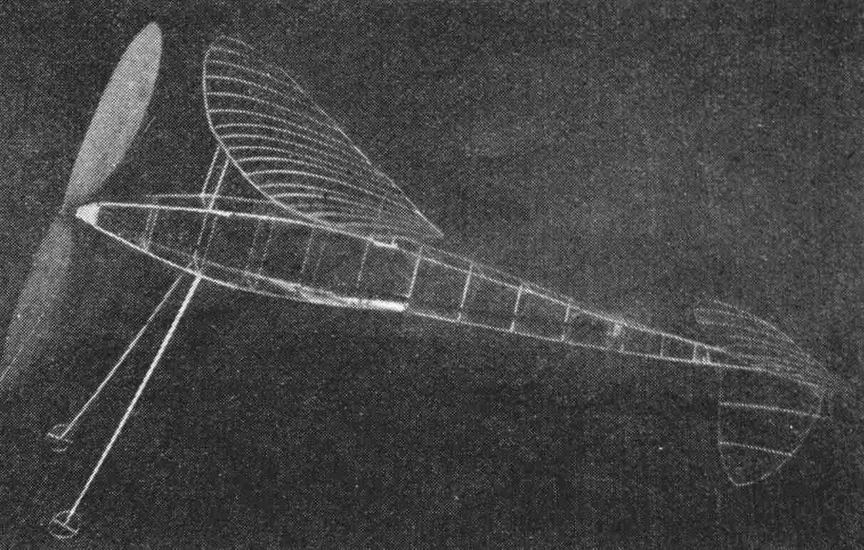
CLASS B FUSELAGE It is rather unusual to see an indoor contest model that really can be called "different," and it is even more unusual when this ship performs so well that it threatens the record of its class. Both these statements can be made of the ship we are about to build. It is "different" for several reasons. First, the ordinary boom is replaced by a microfilm-covered built-up section, which has a double advantage over the hollow boom in that it saves about one-third the weigh and reduces the drag considerably. Second, instead of the paper braces which are used in most models to counteract torque, we use tungsten wire because it is much lighter and easier to apply. In spite of the fact that the original model was handicapped by a low ceiling which restricted the number of turns to 800, two flights of over 6 minutes were obtained a strong indication that flights of 15 minutes are by no means impossible, and the official record is only 14 m. 15s. FUSELAGE The first thing to do is draw up the sides of the fuselage full size. Notice that the fuselage becomes triangular about halfway back. The longerons are 1/20" square balsa, of 5 lb. stock. The cross braces are 1/32 x 1/20" on "edge," that is, with the narrow edge outwards. The boom longerons are cemented in a "spliced" or slanting joint to the fuselage and are 1/32" square. After making the first side, make the second directly over it in order to have both exactly the same. When the sides are dry, cement the back ends together and put in the nose braces and the third set of cross braces. Then pinch the underside of the fuselage together at the proper place and cement these longerons together side by side with dope. When this is dry, the remainder of the cross braces may be inserted. You may now cut off the boom and make a plug for the rear of the fuselage. As shown in the sketch, it is made of two pieces of sheet, the smaller just large enough to fit snugly inside the fuselage end braces. Trim it to fit and cement the boom longerons to the corners of the plug. The fuselage is braced with #4 tungsten wire, which can be bought at one of the model-supply houses that specialize in indoor supplies. Unravel about 2" of wire from the spool, wrap and cement it to one of the corners of the nose, and let it dry. Then unravel about 3' of the wire and attach a 2 oz. weight to the spool and let it hang straight down. Twist the fuselage around so that the wire is wrapped around from corner to corner, around the fuselage and back to the nose again. This operation will require about 12-1/2' of tungsten. Put a dot of cement at the point of contact of wire and wood. After the fuselage is entirely wrapped with wire, put a dot of cement where the wire crosses. When this is dry, try to twist the fuselage. There should be very little twisting. If there is any, tighten the wires. The fuselage is finished now except for covering. The front plug is made of 1/64" quarter-grained balsa as shown in the diagram. The face plate is cemented on and then 1/20" square slivers of balsa are cemented on to it, and the inside then cut away. WING The wing design is what is known as the swept-forward ellipse. In an ordinary ellipse the center-of-pressure line sweeps back; this has a tendency to wash out the wings in flight. In order to eliminate this effect, the ellipse is so distorted that the center of pressure falls on a straight line. The two center-section spars are cut from 1/16" sheet; they are 3/32" at the center tapered to 5/64" where the dihedral is put in. These spars should weigh, together, .003 oz. The tip spars are tapered from 5/64" to 1/6" and they should weigh, all four together, .0038 oz. Of course, the edges of all the spars are rounded off and smoothed with #10-0 sandpaper. The fifteen ribs are cut from a sheet of 1/32" quarter-grained balsa 1/32" deep. They may be cut most easily by the use of an aluminum template. After the ribs have been cut and the spars finished, the spars should be pinned to your full-size drawing. Attach the tip spars to the center spars with a dot of cement. The ribs are fitted into place by cutting off one third the excess from the front and two thirds from the rear, thus getting a uniform section throughout. Make a template for the 1/32" tips from fairly thick cardboard, moisten the strips and bend them around the template. After they are dry, they may be butt-jointed to the spars. When the wing is thus far completed, it is advisable to moisten the spars (while the pins are still in place) in order that they may hold their shape better. The four stilts are cut of light balsa to the dimensions shown and sanded smooth. They are cemented to the wing after it is covered. TAIL Bending the stabilizer and rudder is simple. Make a template of half the stabilizer and, the rudder from cardboard. Then cut three strips, 1/32 x 1/20" and about 14" long, wet them, bend two around the stabilizer former and one around the rudder. After they are dry they should be pinned to a full-size drawing and the ribs inserted. The rudder ribs, of course, are straight. PROPELLER The propeller of the original model was made from semi-carved prop blades. Semi-carved props have three advantages over the regular props: they save time in carving, they are much easier to balance because the grade of wood used in the blades is more nearly uniform, and the pitch is more nearly perfect than you can obtain with an ordinary block. The 14" prop had a pitch-diameter ratio of 1.8, that is, the pitch of the prop was 1.8 times the diameter, or 25.2". A propeller which would be exactly the same could be carved from a block 1 x 1-3/4 x 14". If you carve your propeller from a block, draw your diagonals from corner to corner on the wide face. The tip should be thinned down to about 1/16 " and the hub to about 3/32". Then sand progressively, starting with #2 and ending with 10-0 paper, until the blades are 1/16" at the hub and 1/64" at the tips. The blade should have a camber of about 3/32" deep and the cross section of an airfoil. Make a template of the blade shape, shape your blades to fit it, and insert your shaft. The finished propeller should weigh about .016 oz. COVERING Cover the model with microfilm. The wing should be covered in one piece and the dihedral put in by breaking the tips upward. If the film at the dihedral is "floppy," it may be tightened by holding the wing about a foot above the burner of a gas stove when the flame is turned down so low that it almost goes out. LANDING GEAR The landing gear is made of two spars cut from 1/16" sheet balsa 1/8" wide tapered to 1/16" and sanded smooth. Axles are made of wire .012" in diameter and cemented to the spars. The wheels are easily made by bending a strip of balsa 1/64 x 1/20", soaked In water, around a bottle neck 3/4" in diameter. Then the wheels are sliced off, joined, and the spoke inserted. Slip the wheels over the axles. ASSEMBLING AND FLYING Cement the landing gear to the fuselage, and the stabilizer and rudder to the boom. Notice that the rudder is underneath. Make sure that stabilizer and rudder are exactly perpendicular to each other. Cement the wing stilts to the wing and to the fuselage at the indicated position. Drop a loop of 3/32" brown rubber 19" long through the fuselage, attach the prop and wind up the motor to about 500 turns. Attach the rubber to the rear plug hook with an S hook and put the plug into place. Set the model on the floor, the two wheels and the rudder touching, and then release it. The model should hop off, turn in 40' circles, and reach an altitude of about 30'. If there Is a tendency to dive, the wing must be moved forward; if there is one to stall, backwards. The rudder may be warped for turn. Increasing the length of the rubber is an effective method of keeping your plane off the rafters. By increasing the length you add weight to keep the plane down and you also increase the possibility of greater endurance. A lubricated 19" length of 3/32" rubber can take 2,300 turns with ease.
Scanned From November 1936
|
||||||||||||||||||||||||||||||||||||||