|
Building the Arup Flying Wing If You Wish to Build and Fly One of the Most By GORDON ENGLEHART
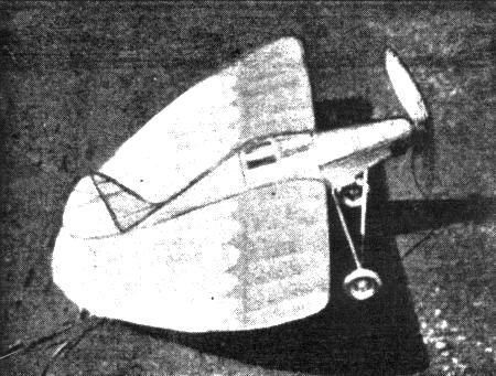
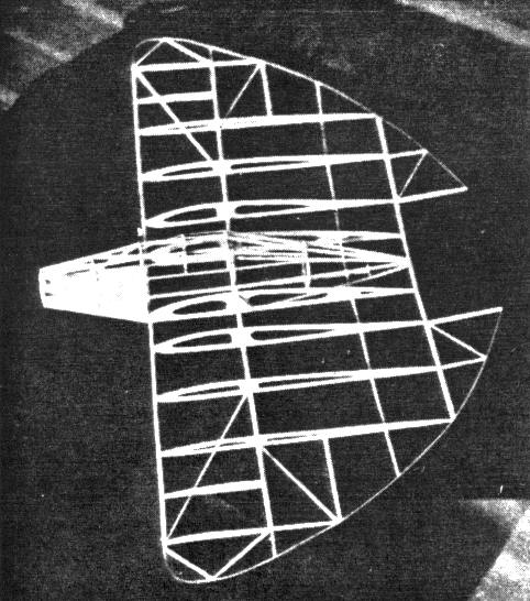
THE Arup Flying Wing is one of the many lightplanes which have been produced recently as a try at the goal of the "flivver plane" or a plane which the common man would be able to buy and fly. The Arup is perhaps the nearest approach yet to this ideal. It is light, yet strong, low-powered, still quite fast, has a low landing speed and is very economical to run. The original was powered with a 40 hp. Continental engine, had a top speed of 97 m.p.h. and landed at only 23 m.p.h. There was practically no attempt made at streamlining (as is usually the case with experimental models) so that the top speed could have been raised well above the 100 m.p.h. mark if resistance had been cut down. So much for the background. The model presented here is an excellent flier and is very sturdy. These models never seem to crack up; they merely disintegrate from old age and abuse. If you take time and work carefully, you will have a flying model you can well be proud of. One more thing before beginning the instructions. Many beginners have gotten so accustomed to having everything done for them in the way of completeness in plans and instructions, that they have left their sense of initiative and inventiveness, far behind. That is unfortunate because model building is supposed to develop new thoughts and ideas so that if everything is practically done for the builder, all benefit is lost. For this reason, several small details have been left out of the plans but not out of the instructions. All these parts may be made very easily by studying the instructions carefully; and it is hoped that this will set our embryo model builders to work at their own problems instead of merely copying the results of somebody else's labor. Now that I've had my say, let's get down to work. Wing Frame The wing is made first because it is the foundation of the plane. The body is built directly on the completed frame, so there is no other place to start. Start by cutting out two of each rib section of 1/16" sheet balsa. They are hollowed out as shown on the plans to lighten them. Now take two pieces of hard 1/8" sq. balsa and mark the positions of the ribs with a pencil. The pieces should be about 26" long so that you will have a little extra. The distances for the rib spacings will be found on the assembly drawing. The two No. 1 ribs are 3" apart ; the No. 2 ribs are 1-3/4" from the No. 1 ribs; No. 3 ribs are 2-1/2" from No. 2; No. 4 ribs are 2-1/2" from No. 3 and No. 5 ribs are 3-1/2" from No. 4 ribs. Fit the slots of the ribs into the upper wing beam at the proper places and true them up. Then crack the beam so that there is 3/8" dihedral on each side starting from the No. 1 ribs. Now put the lower beam into place, cracking it where it fits into the No. 1 ribs. Cement all joints securely and true the frame up. Next the rear spar is put in. This is a piece of hard balsa 1/8" x 1/16". After that, the trailing edge is put on. This is a piece of hard balsa 1/8" x 1/16". Pin it onto place while the glue is drying and check over the model to see that everything is still lined up perfectly. Now put the leading edge on. This is a piece of the hardest 1/8" x 1/16" you can get. Now go over the frame carefully and glue any joints which are not solid. Now the wing-tips are bent from 1/16" sq. bamboo. Although no full-size outline is shown on the plan, the shape can quickly and accurately be gotten from the assembly drawing. Bend the tips over a candle flame to fit the wing frame. The wing tip extends from the leading edge to the rear edge of rib No. 5 and then to the trailing edge. Next, the trimmer flaps are made. They are made in the usual way of making tail surfaces, by pinning the work directly to the plan. When done, they are cemented to the trailing edge so that the trailing edge shows a gradually rounded surface. Now, go over the completed wing framework with sandpaper and you are then ready to start the fuselage. Fuselage The fuselage is started by cutting out 1 of each former of 1/16" hard sheet balsa. Now take formers 2 and 3. Former No. 3 is glued to the main wing beams so that the bottom notches are just below the bottom of the ribs. Former No. 2 is glued in a line with station No. 3, and the line formed by the bottom of the ribs, to the leading edge. Let these formers dry well for they are the foundation of the body and they must be accurate if the body is to be accurate. Next, take four 18" strips of 1/8" x 1/16" hard balsa and with a pencil, mark with a pencil where formers No. 1, 2. 3 go. Cement all these pieces into the side notches in formers 2 and 3 at the pencil marks and let them dry. When they are dry, crack each piece at former No. 2 and bend them in. Now, take former No. I and put it in where the pencil marks are. Cement it securely and line it up accurately before the cement dries. The rear hook is put in now. It is a piece of stiff music wire bent into a hook and cemented to the trailing edge in the middle of the space between the two No. 1 ribs. Next, the four stringers are cracked at station 3 and bent in and cemented to the trailing edge at the middle. Former No. 4 is now slid into place back of station No. 3 and cemented. Now the rest of the stringers are cemented into place. Pieces of l/8" x 1/16" balsa are cemented midway between formers 1 and 2 and parallel to them. When they are dry, diagonals of the same size are put in as shown on the assembly drawing. The bottom of the space between formers 1 and 2 is covered with sheet balsa 1/16" thick. Next, the turtlebacks are cut out and cemented on. They are of 1/16" sheet balsa. The front turtleback is cemented half-way between formers 2 and 3: the rear one is cemented to the front of former No. 3. Balsa stringers are run from the rear turtleback to former No. 4. Thin strips of bamboo are run from the rear turtleback to the front one, cracked, and cemented to former No. 2. A space should be left open at the bottom at the rear so that the rubber may be changed easily. This is done by putting a spreader bar across the two bottom stringers at the rear and leaving this space uncovered. Now, go over the whole body with sandpaper and then the body is finished. Tail Surfaces The tail surfaces are made in the usual way of 1/16" sq. bamboo and 1/8" x 1/16" balsa. Work right on the plans. When they are done, sandpaper them carefully and then go over all the joints to make certain that they are securely glued. Finishing Up This is a section not found in most articles, but here it is necessary. Go over your model and see where it needs extra bracing. It will need some at the wing tips and along the trailing edge. The details of the bracing I used may be found by looking at the framework picture. After you have put in all necessary bracing, sand the joints, and you are then ready for covering. Covering I can say very little about the details of covering. You should work carefully and use small pieces on the body and large pieces on the wings. The cockpit should first be covered with cellophane, then the body, wings and tail surfaces with Jap tissue. Many interesting color schemes can be worked out for this model. I used white with blue scallops on mine and found it to be very effective. However, color scheme is purely a matter of personal taste. After you have finished covering the model, first spray it with water and then give it two coats of a good grade of dope. Now glue on the stabilizer and rudder. The stabilizer may be either cemented on or hinged with copper wire. I prefer to hinge it for easy adjustments. Landing Gear The landing gear is formed of four bamboo struts and a wire retainer. The front struts are 5-3/4" long and the back ones 5" long. The struts are streamlined, then one end is sharpened and burred and fitted into a hole specially prepared for it in the fuselage. The landing gear should have a spread of 5-1/2". Next, a wire retainer is bent from stiff music wire and cemented into place. It is a combination spreader bar and axle in one piece and its shape may be gotten from the assembly drawing. It is bound to the bamboo struts with thread and cemented firmly. Wheels are put on the axles and the ends of the wire bent up. Wheels may be of practically any type with the exception of balsa as they would be too light. Wheels should be 1-3/4" diameter. A tailskid is bent from wire and cemented to the trailing edge. Propeller The prop is carved from a block 11 x 2 x 3/4". Leave the blades fairly thick at the hubs, about 3/16", and taper them to 1/16" at the tips. Balance it carefully after you have finished carving and give it two coats of dope. Carve a nose block out of a block of medium-hard balsa to the shape of former No. I and round it off in front. An aluminum tube is put through the nose block to act as a bearing. A square of balsa is cemented to the back of the nose block which just fits the opening in former No. 1. Then the prop is put on, the rubber installed, and you are ready for flying. Flying I don't believe you will have any trouble with this plane, but if you do, treat it just as you would any ordinary model. If the model stalls, add weight to the nose or turn the flippers down (the latter being preferable up to a certain point). Two cylinders may be put on the nose, one on each side for realism. One more thing, do not fly this model when it is very windy as the large area of the wings with the very light wing-loading allows it to be taken for a ride by a stiff wind. If you like, free-wheeling may be put on the prop to increase the glide to a point where the model will soar beautifully. Combine free-wheeling with winding with a winder and you have the net result of some very pretty flights. Good Luck! Scanned From September 1936
|