|
A Rubber-Powered Pursuit Model Editor and Designer
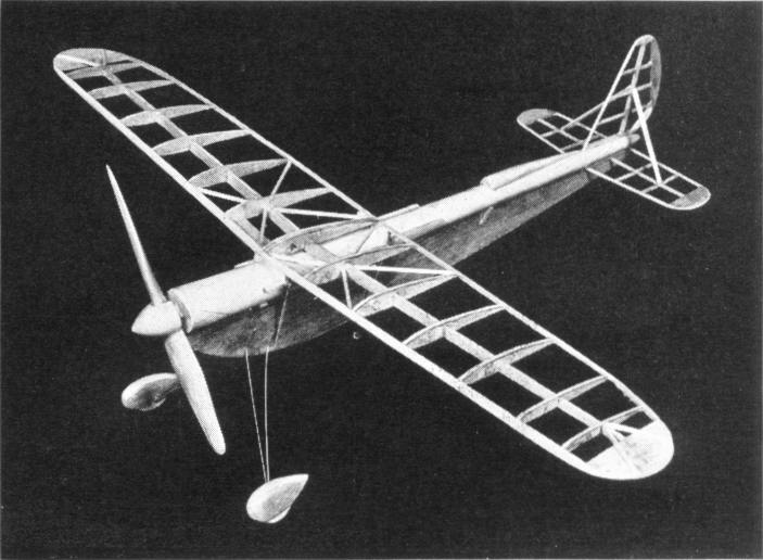
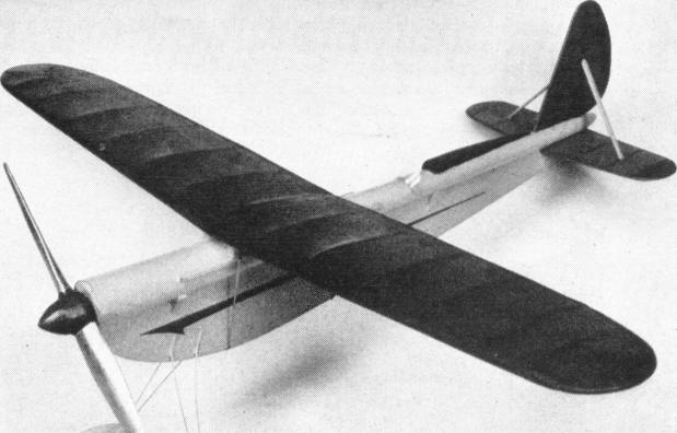
DUE to the many requests for a rubber-powered model, we have designed a snappy little pursuit that can be built up in a very short time. Its construction is so simple that the most inexperienced builder will have very little difficulty in constructing it. This model was primarily designed so that you might build it during your vacation and so that you will have many enjoyable hours flying it this summer. As you will note on the plans, a rubber motor is cleverly concealed within a paper tube which will withstand the severest strain. The plans are full-sized so that you might work directly from them. Use ordinary waxed paper over the plans to prevent parts from sticking to them while being worked on. Construction of Fuselage The tubular part of fuselage is made of ordinary drawing paper such as used in drafting courses. The paper should be an oblong piece rolled into a tube as shown on the detail of plan. After the proper shape is obtained, slip rubber bands at three different points along the tube. Apply cement along the spiral seam and let dry. Next trim off either end so as to fit in the nose and tail blocks. From a 3/16" thick piece of soft balsa, cut the lower part of profile fuselage. This is attached to the tubular piece with the addition of small braces on either side. Construction of Landing Gear From .032 piano wire, bend one left and one right landing gear. As you will note, each side is made from one continuous piece, being bound at the bottom with thread. Holes in the fuselage may be either drilled or burned through. With a needle and thread, bind the landing gear struts securely to fuselage. After this has been accomplished, a liberal amount of cement is applied over the thread and landing gear wire. The tail skid is an ordinary piece of piano wire inserted into the rear of fuselage. Construction of Wing The ribs are cut from 1/16" thick (or less) balsa. Next cut and sand the leading and trailing edges to their proper shape. The leading edge and spar are tapered, so a little added work is required in order that they may be held to a true curve. The wing tip is made from 1/16" sheet balsa braces with two 1/16" square diagonal braces, as shown on top view of right wing panel. Please note that ribs "A" in either wing panel are cemented on an angle so that the dihedral is automatically built in. Front and rear wing supports are attached to wing after it has first been covered with tissue. Construction of Elevator and Rudder Construct these from 1/16" square balsa and sheet wood, upon a flat surface, using pins to hold the framework together in order that the cement will have a chance to dry. These are attached to rear of fuselage after they have first been covered with tissue. Covering the Model In covering the wings and tail surfaces, cover only a section at a time. For instance, from the top of the wing panel from rib "A" to the tip, top side only. Use a light grade of model airplane dope in fastening tissue to framework. The bottom side of wing panel is covered in very much the same manner. Stretch the paper in order to remove as many wrinkles as possible with out causing any undue strain on the framework. Each wing panel is now given a light coat of water, top and bottom sides. Pin around outer edge upon a flat surface to prevent any warpage while drying. Carving Propeller This type of propeller is known as the true pitch. If it is carefully cut into blank shown on the plan, the carving will be greatly simplified. It is very important that the propeller be perfectly balanced in order that you gain the maximum results. A spinner may be added if so desired. All details such as wing slides, head rest and wind shield are clearly explained on the plan. Flying the Model The rubber motor is comprised of from four to six strands of 1/8" flat rubber. The latter amount would naturally give more speed but less duration. After the wing has been attached to the fuselage by means of rubber bands, place one finger at either end of wing at a third of the way back from leading edge. If model is properly balanced, nose will point down slightly. Next glide model gently from hand on an even downward angle (into tall grass preferably) in order to prevent any damage while testing. If the nose should drop suddenly, move wing forward slightly. If the nose raises abruptly when launched, move wing slightly to rear. When the proper setting is had, model should glide gently to ground. A test flight may now be made by winding the propeller 75 to 100 turns. END Scanned From October 1938
|