|
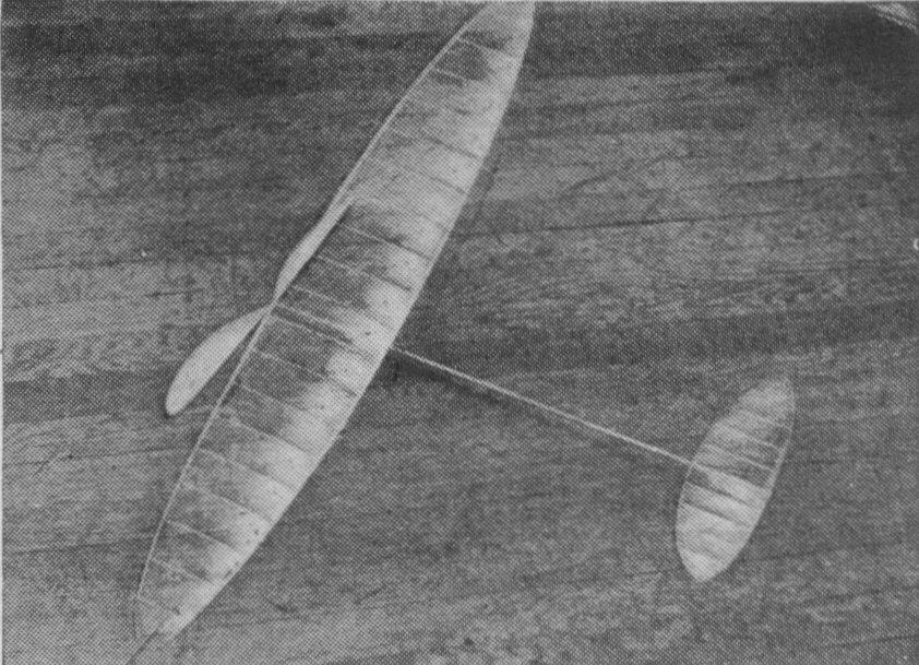
The Canard An indoor pusher of advanced design and simple construction - an ideal project to inaugurate the indoor season By Lawrence N. Smithline
THE INDOOR PUSHER is almost as extinct as the Dodo bird. Six or seven years ago at least one pusher could be seen at the regular Saturday sessions at the armory. Not so to-day. Their extinction may be attributed to the conviction of most model builders that the limitations of a pusher as regards endurance are more numerous than those of a tractor. Still, in its defense, it may be said that pushers, besides providing a great deal of fun, have much to teach the model builder. Pushers are really tandem planes for both the wing and "tail" surfaces do the lifting at all times. This is plainly evident when one notes the location of the center of gravity of the plane in relation to the wing and tail. Another outstanding characteristic of pushers is that the fin is ahead of the center of gravity. The reason for this is that most pushers require their directional centers farther forward to prevent spiral instability. The building of a pusher brings up no absolutely new problems, so that we can get right down to work. There is, though, a minor constructional difference dictated by convenience rather than by necessity; that is the carving of a left-handed propeller instead of a right-hand propeller. This will facilitate winding the motor, because it can be wound in the conventional way and still push rather than pull. WING The wing is what is known as the "swept-forward" ellipse. It is an ellipse distorted so that the one-third points of the ribs lie on the same straight line. The wing is exactly the same as was used on the Class "C" Tractor described in the January 1937 issue of Air Trails. You can save yourself considerable time if you still have the draving of the wing. If not, you will have to take time out to make a new drawing. The wing is built up in three sections. The spars are made of light balsa 5/32 x 1/16" tapered to 1/16" square at the tips. Round all the corners; sand them smooth with #10-0 sandpaper; pin them to the drawing and wet them with water. Cut out the ribs from 1/32" "C" stock balsa. ("C" stock balsa has a speckled appearance. It is very stiff but light.) After the water put on the spars has evaporated, cement in the ribs. As you work out toward the tip it will be necessary to shorten the ribs. Do this by cutting off one third the excess length from the front end and two thirds the excess from the rear. This will tend to keep a more uniform wing section. Make a cardboard template of the tip and bend two strips of 1/32" square balsa, soaked in water, around it. After they have dried, cement them to the tip sections. Cover the three sections separately with microfilm and then cement the sections together with 1-1/2" of dihedral under each tip. Make wire clips to fit the fuselage and cement them to balsa stilts each two inches long. The pusher wing should have no angle of incidence, so after the stilts have been cemented to the wing make sure that the distance from the lower edge of the wire clips to the front and rear spar, are the same. This completely finishes the wing. TAIL AND FIN The tail of a pusher is built in the, same way as that of a tractor, except that the two halves of the tail are cemented together only lightly before covering, in order that the dihedral angle ought be put in later. Make a template of one half the tail from cardboard, bend two 1/32" square soft strips which have been soaked in water around the template and allow them to dry After they have dried pin them to a drawing of the tail shape, cut ribs from 1/32" "C" stock and cement them in place in the same manner as the wing ribs were installed. Put a drop of cement at the joint of both bent strips. Use no more cement than is absolutely necessary to hold them together. Make a template of the fin shape and bend a strip of 1/32" square balsa around it in the same manner as the tail. Cement the rib in place and cover both tail and fin. After the tail is covered put in the proper amount of dihedral by cracking the cement joint at the center, raising the tips and recementing it. After the cement has dried, heat-treat the film at the dihedral in order to remove any wrinkles in the film. Heat-treating is merely passing a hot wire under the film at a distance of about 1/2". Wrinkles call be seen to dissolve with the application of heat. MOTOR STICK AND BOOM The motor stick and boom for a pusher are made in exactly the same way as that of tractor. However, the pusher boom is somewhat shorter than the tractor boom. Make a motor stick former of hard balsa 5/32 x 3/8" at the center, tapered to 3/32 x 1/4" at the ends and I5" long. Round the corners and smooth the former The blank is made of 1/32" sheet 1-1/8" at the center, tapered to 3/4" at the ends and 15'' long. (The wood should be light but as stiff as possible.) Soak the blank in hot water, bend it around the former, and bind it with 1/2" wide bandage. Allow the water to dry out, remove the bandage, and then sand it with #10-0 sandpaper. Then you may cement the seam caps thrust bearing, and rear hook in place, after you have taken the formal blank off the former. Make the boom former of hard balsa, 3/32 x 3/16" tapered to 1/16 x 3/32" and 9" long. Round the edges and smooth the stick. Make a blank of 1/64" light sheet balsa 5/8" tapered to 3/8 x 9" long. Proceed with it as was done with the motor stick -- soak, bind, sand, and cement the seam. After it is finished cement it to the motor stick with the front end raised 3/16". PROPELLER The propeller of the pusher is left-handed, as explained previously, for the convenience of winding. It is carved from a block of 4-lb. balsa 1-3/4 x 1 x 6", or from a semicarved 16" propeller of pitch-diameter ratio 1.6. Finishing a semicarved propeller will save you about two hours, as well as give you a more perfect pitch propeller. In both cases carve the concave sides first and completely finish them before proceeding to the convex sides. Smooth the blades with #10-0 sandpaper. Make a template of the blade shape and cut the blades to fit. Make a shaft of .016 wire and insert it into the propeller in what would ordinarily be backward for a tractor. Coat the hub with cement. ADJUSTING AND FLYING Cement the fin onto the boom in the position indicated in the drawing and then cement the tail in place. Put the wing on the motor stick, remembering that the tying goes on in reverse from the ordinary way; that is, with the trailing edge toward the propeller. Insert the propeller shaft into the thrust bearing and put a loop of 7/64 x 1/30 x 17" brown rubber in place. Glide the model. If it stalls, move the wing forward; if it dives, move it backward. Note that you do the opposite to a pusher to correct dives and stalls, but the same treatment is used for both pushers and tractors in cases of washing in or out. After a good glide has been obtained, wind the motor about 500 turns. The method of launching pushers is somewhat different from tractors. It is done as follows: Hold the model with one hand only. Grasp the propeller hub and thrust bearing with your thumb and index finger. The middle finger supports the motor stick. Raise the model to eye level and holding it at a slightly positive angle, thrust the model forward at approximately fling speed, and release it. The model should fly it circles about 40 feet in diameter. If the Model tends to dive, or stall, correct it as explained previously. More full winding may tend to dive the plane. Correct this by moving the wing forward. The model under full winds and good conditions should break 20 minutes. To date, the highest time known to be done with pushers is 16 minutes. Let's see what you call do about it.
Scanned From December, 1937
|
||||||||||||||||