|
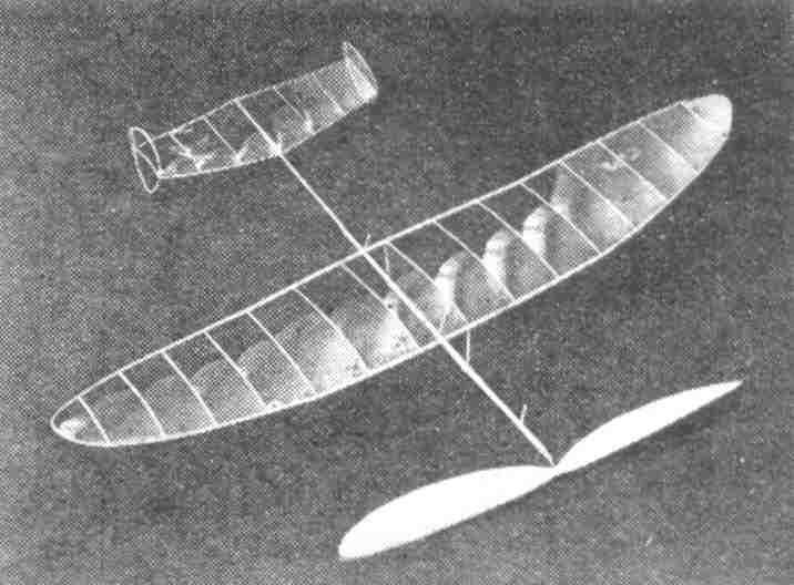
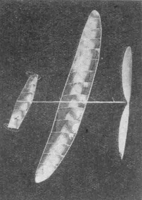
THE ZEPHYR An interesting, Class B, twin-tailed indoor model designed by an expert to contest requirements. By Lawrence N. Smithline
CONTESTS have made the "ship of the day" the class "B" model. A year ago the larger models were the most popular, as model builders apparently believed then -- and they still do -- that the class "C" job was the most consistent performer. Now, however, if model builders are to be contestants, not only must they build smaller models, but they have been forced to retrogress in building technique, as rules of the greater bulk of contests prohibit any built-up parts. This model has been specifically designed for these rules. It has a solid, braced motorstick and a solid tail boom. This ship is set apart from the ordinary "run - of - the - mill" model because of the twin rudders. The purposes of using the twin rudders are: first, it enables us to use a smaller tail because it greatly increases its efficiency. Second, it cuts down the tendency to twist the boom. Both of these features will save us weight by allowing us to cut down the boom dimensions. WING The wing of this model is elliptical and of low-aspect ratio. Low-aspect ratio was used because it cuts down the weight of the wing. Draw the wing out full size and make your spars from very light 1/16" sheet balsa 5/64" at the root and tapered to 1/16" at the dihedral. The tip section spars are made of 1/20" stock, 1/16" tapered to 1/32" square. Round all the edges, pin the spars to the drawing and moisten them with water. Make a template of the rib section from stiff cardboard and cut out the 15 necessary ribs in the following manner. Lay the template on a sheet of 1/32" "C" stock (quarter - grained balsa, which has a speckled appearance) and cut around it. Then slide the template down 1/32", but parallel to the first cut, and slice it again. This will form a rib. Repeat this process till all the required ribs are cut. Cement the ribs into place, cutting off 1/3 the excess length from the front and 2/3 the excess from the rear. Now make a template of the curved tip from stiff cardboard and bend two strips of soft 1/32" sq. stock, soaked in water, around it. Let them dry, remove them from the template, and cement them to the tip spars. Tack the tip spars to the center section with a small dot of cement, remove the pins, and the wing may now be covered in one piece. After it has been covered, crack the cement joint at the dihedral and raise each tip one inch. Clip stilts are made of 1/20" by 3/32" stock, the front one 2" long and the rear 1-7/8". Make the wire clips to fit the motorstick and cement them to the stilts. Then cement the assembly to the center of the wing making sure that they are perpendicular to the spars, and in exact alignment. TAIL AND RUDDERS Flight tests have justified this small tail. Because of the tip rudders this tail is as effective as one with almost half again as much area. The tail spars are cut from medium balsa sheet 1/32". Ribs are cut in the same way as the wing ribs, but the section used is a modified 23012 centerline. The 23012 is the most efficient section as determined by the NACA. The rudders are made by bending two strips of 1/32" sq. soft balsa soaked in water around a lighted 50 watt electric bulb. After they have dried, they should be fitted on a drawing of the rudders and the spar should be inserted. Cover the tail first and cement the rudders in place. Then cover the tip rudders. In covering the tip rudders DO NOT stick the microfilm to the end ribs of the tail. MOTORSTICK AND BOOM The motorstick is braced in order that it be reasonably light and still come within the rules which state that it must be solid. It has a round section as the round section gives the least angle of twist for a given crosssectional area. The motorstick is made of medium light 3/16" sq. balsa. 12" long. It is tapered to 1/8" square at both ends and the edges are completely rounded off to give a circular cross section. For added torsional rigidity, the stick is wound with #3 Tungsten wire at an angle of about 30° with the horizontal and in such a direction so that by twisting it in the same way as the fully wound motor, it would be in tension. Cement the posts for the wires, which counteract bending, in place, and string the #3 tungsten wire over it. Then cement on the thrust bearing and rear hook. The boom is made oval in crosssection. It is rounded out from a strip of medium balsa 1/8" by 5/64" tapered to 3/64" square and 8" long. After it is rounded out and smoothened, cement the tail and rudder unit (which has already been covered) in place. Then cement the boom to the rear of the motorstick with the thin end raised 1/8" for negative incidence. PROPELLER The propeller may be made from either a solid block, or from a semicarved blank. If you decide to carve a block, one of the following dimensions is recommended -- 7/8 x 1-1/2 x 14". It should be carved in the following manner. First lay out the diagonals on the broad faces, carve down to these diagonals with a sharp knife (leaving about 3/16" at the center for the hub) and sand the edges smooth. You may now carve the concave sides which should be done first. Completely finish them even down to polishing with #10-0 sandpaper before starting the other side. Use a knife on the convex sides till the blades are 1/4" thick, then you may use a razor and finally, varying degrees of sandpaper till you are using #10-0. When sanding never rest the blades on anything else but your fingers as otherwise you may change the pitch of the blade, or worse yet, you may break it. Make a template of the blade shape on paper and trim the blades to fit. Smoothen the edges with #10-0 sandpaper and insert and cement the propeller shaft in place. Should you have decided to use a semi-carved propeller, use one that has a pitch diameter ratio of 1.6 and a diameter of 14". You will find that it will save you a great deal of time in carving and will also probably be more efficient. Of course, carving it will be similar to the carving of the block, but you will first have to cement the blades together. ADJUSTING AND FLYING Clip the wing over the motorstick about 3-1/2" from the thrust bearing and bind the clip with silk thread to prevent the wing from sliding around the stick. Insert the propeller in the thrust bearing, hang a loop of 5/64" brown rubber 16" long from the propeller shaft and rear hook and glide the model. If it dives, move the wing forward. If it stalls, move it rearwards. After you obtain a good glide, wind the motor about 400 turns and release the model in flying position. It should hold its altitude for at least one complete circle of about 40' in diameter. If it does not turn enough, bend both rudder tabs over an equal amount till the proper circle is obtained. If it does not hold its altitude, try moving the wing forward. (Your model is probably a bit too heavy if this treatment causes it to stall and it may be remedied by decreasing the blade angle). If, however, the model has stalled, bend a little negative in the thrust bearing. Next, wind the model more fully and observe its flight. If necessary, make the same kind of adjustments. WEIGHTS SPECIFICATIONS Scanned from April, 1938
|