|
The
original model was burned by smoke screen apparatus before finished photos
were made, but it proved to be a fine flier |
|
|
The
original model was burned by smoke screen apparatus before finished photos
were made, but it proved to be a fine flier |
|
THE GREAT SOPWITH
‘CAMEL’
by JOSEPH H. WHERRY
EVERY now
and then in all lines of endeavor a truly great event takes place. This is true
in aviation as well as in other industries. The event which the author has in
mind took place in late 1917 - it was the appearance in squadron strength of
the famous Sopwith Camel scout fighters
over the Western Front.
No sooner
had the Camel received its baptism of
fire than such aces as Collishaw, Little, Frew, MacLaren and others too
numerous to mention began to roll up impressive numbers of victories at the
expense of Kaiser Wilhelm's Imperial German Air Force. Even the great Baron
Manfried von Richthofen had the somewhat disaster-filled distinction of being
shot down over the Australian sector of the British lines by a young Canadian
airman, Capt. A. Roy Brown, who finished the war with 13 Jerries to his
confirmed credit. Yes, Brown polished off the great Red Knight who had about 82
Allied aerial scalps credited to himself. Richthofen, at the time of his death
early in 1918, was flying a Fokker Triplane D.R.1.
Here are,
just a few of the Camel's points of
interest: span 28 ft.; length 13 ft. 9 in.; speed about 115 mph, and cruising
time 2-1/2 hours. It could climb to 5,000 ft. in 5 minutes,
and below 12,500 ft, it was the most maneuverable ship on any front any time
during the war. All of this remarkable performance was accomplished with a 130
hp Clerget Rotary. Later in the war Camels
were reaching the front equipped with 150 hp Bentley, and finally 230 hp
Bentley motors. Camels even served
the British Royal Navy as shipboard fighters. The decks of the old carrier
Furious of the Royal Navy echoed to the battle rhythm of the historic Camels.
Statistics
show that squadrons of the Royal Flying Corps destroyed at least 905 enemy
aircraft, while the Camel units of the
Royal Naval Air Service destroyed over 370 along with one zeppelin and several
kite balloons. This gives a grand total of at least 1275 enemy aircraft as
having fallen to the tune of guns manned by the young British pilots. This does
not count the many victims of Camels
flown by the Yanks, Belgians and even French; yes, even the latter purchased
some Camels for their
"Chasse" escadrilles. With their two twin Vickers guns (sometimes
one Vickers was mounted, supplemented by a Lewis gun over the center section
which was uncovered for better visibility), the Camel pilots proceeded to whip many times their number of Jerries.
During the
1920's the Sopwith firm underwent a change in organization and emerged as the
now famous Hawker Aircraft Co. The established and proven aeronautical design
principles remained, however, and the modern Hawker Hurricane, Typhoon, and
Tempest fighters of current fame are the direct descendants of the Sopwith Camel, Snipe, Ddlphin, etc.
With this
background in mind, you can readily see that no modeler's tarmac is complete
without one of the greatest fighter planes that ever worried the "Master
Race." If the accompanying plans and instructions are followed, you will
be rewarded with a model that will be a beauty to behold, and one that will be
a thrill to fly.
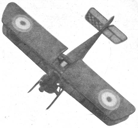
One word of
caution: the author strongly recommends that no accessories such as
smoke-screen apparatus be installed. The writer, when he built the model
pictured here, was interested in various gadgets. If he had not been in such a
hurry to try out such miniature luxuries he might still have had his model Camel; at least he would have had a
complete set of photographs to remember it by. That smoke-screen gadget, which
was actually successful to a certain extent, caused the model to burst into
flames after one particularly beautiful takeoff. All the friendly Gremlins on
the model flying field could do nothing and the model was destroyed even before
the decorative checkerboard design was applied to the entire tailplane. Just
build a good model, fly it in an orthodox manner, and you will avoid learning a
lesson the hard way as the author did to his disgust.
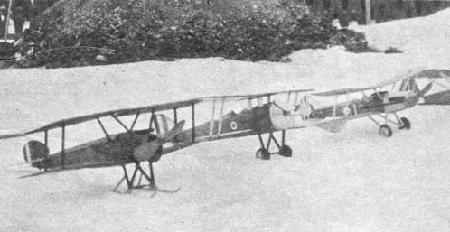
The model
shown wore skiis throughout its short career and it performed spectacularly on
snow and ice. Wheels can be easily fitted; however, if you have never had the
experience of flying a model with ski gear here is one that will provide many
thrills.
FUSELAGE - We begin by building the two
sides of 3/32" square medium grade balsa. Note that this basic framework
is shown on side and top views by the solid black construction. The two sides
are joined together, first at the tail post, then working forward. Crossbraces
of the same 3/32" square balsa are placed in like positions at top and
bottom of fuselage. While this structure is drying, cut the side formers (two
of each) from 1/32" sheet balsa and cement in their proper places. Cut
formers 1, 2 and 3 from 1/16" sheet balsa and cement in place on top of
the fuselage frame. Now, from 1/32" sheet balsa, cut formers 4, 5, 6 and
7; install in their proper places. All stringers on fuselage sides are of
1/16" x 1/8" hard balsa; stringers on fuselage top aft of the cockpit
are 1/32" x 1/16" hard balsa; and the two short stringers which join
formers 1 and 2 forward of cockpit are 3/32" square balsa. When all
stringers are installed, sand the entire framework to make it as smooth as
possible.
The author
suggests that a strong grade of bond paper be employed to cover the space
between 1 and 2 top formers as well as to form the cockpit. Using small pieces
of 3/32" flat soft balsa, fill in the space on each side of fuselage where
the wings connect with the fuselage at the lower longeron. This filling in has
been noted on the plans as the Wing Support Gusset. With razor blade and
sandpaper, work this support gusset down to where it blends in with the side
formers and lower longerons. You will find that this makes a very rigid
assembly to which the lower wings and the landing gear struts may be easily
joined. Insert the rear motor hook of .004 music wire. From soft balsa carve
the solid balsa block which fills the space between No. 1 former and the
cowling on fuselage top; sand to a smooth shape, cement in place, and sand
further so as to cause it to blend in with fuselage.
The
fuselage framework is now complete; we need only the cowling to complete this
unit. The cowl is formed of seven layers 1/8" medium grade sheet balsa.
With a compass, mark the correct size circles and cut out with razor blade or
scroll saw. (The radii can be easily determined from the cross sections shown
in side view on Plate la.) Note that the third layer from the front is solid
except for the small 1/4" diameter hole at center; note also the two
smaller circular layers which form a base for the nose plug. When all cowl
circles have been shaped, cement together by laminating and allow considerable
drying time. When dry, carve and sand to the correct profile. Note that the
cowl is irregular in shape on the bottom when viewed from the side. This
irregularity allowed for the escape of the hot castor oil laden exhaust fumes
of the Camel's rotary motor. The
author chose to lighten his model by not including a detailed motor inside the
cowl; this motor, if like that on the original ship, should revolve. However,
if some of you wish to include a detailed motor, you should have no trouble
finding details in old issues of this magazine. The cowling is cemented flush
to the front of the framework; and with this operation finished our Camel fuselage is complete.
EMPENAGE - Both rudder and elevators are
easily built directly over the plans on Plate 1b. In the interest of lightness,
because this quality is most essential in flying scale models, the author
recommends that tail surfaces be constructed of 1/16" flat medium weight
balsa. Widths of the various members may be taken from the plans. The tail surfaces
of First World War aircraft were generally speaking flat, the only deviation
being the very thin trailing edge as shown in the cross section of the
elevators. A thorough sanding with very fine sandpaper will do much to further
a successful covering job.
WINGS - The only difference between
upper and lower wing panels is shown on Plate 2 by means of dotted lines. To
make a set of plans for the left wings, merely trace the right wing panel and invert
your tracing. The wings are best constructed of medium grade balsa; directly
over the plans, the dimensions are noted on the plans with the exception of the
tips which are made from 1/16" flat scraps. The author recommends straight
grained pine be used for the wing spars; this adds strength to the very thin
wing section. Note that two small center section strut supports are installed
in the top wing panels flush with the bottom surface of wing. Be certain that
you install the two small gussets at the root ribs of each panel.
The center
section is also constructed directly over the plans. The ribs are cut from
1/16" sheet balsa as are the main ribs; three are needed. When all wing
panels have been constructed, carve leading and trailing edges to the proper
cross sections shown on the rib pattern. Some builders may prefer to shape
these parts before they have been cemented to the wing structure; however the
author prefers to shape them, after assembly, with a razor blade. When all
panels are complete, sand entire structure with fine sandpaper. Most dime stores
sell a number of small "emery boards" of the type used by women on
their finger nails; you will find these of great use in sanding the completed
frames and in preparing them for a smooth covering.
STRUTS - The patterns for the landing
gear struts, landing gear spreader bar, and the center section struts are found
on Plate 2. The interplane struts can be measured directly from the side view
on Plate 1 (since interplane struts are installed vertically, there is no
distortion). All struts are cut from 1/8" x 5/16" hard balsa and are
streamlined, sanded and clear doped. The spreader bar is made from medium balsa
and is 3/16" thick and 11/16" wide. The two 1/8" square pine
axle supports are cemented firmly in notches. Streamline the spreader bar as
shown and sand well, then follow with a good coat of clear dope.
Realism can
now be added to these struts by color, doping them with a brown dope. This will
resemble the struts of early combat planes. Likewise, doping the struts before
assembling will aid in securing a neat model; doping struts in the vicinity of
a good covering job is not conducive to neatness.
COVERING and DOPING - Because most First War Camels were of rather dull coloring, the
author suggests a khaki or olive drab colored tissue be used. This will give a
desirable color, and at the same time will tend to hold down the weight of the
finished model. Covering should always be done with the grain of the tissue
running the long way of the part being covered. Because of the concave shape
of the undersurface of the wings the tissue adhesive should be applied to each
rib. One piece of tissue can be used for each side of each wing panel with the
exception of the tips which should be covered with a small separate piece. The
fuselage is covered with a series of small pieces, and the tail surfaces can
easily be covered with one piece to each side. Be certain the covering is
neatly cemented around leading and trailing edges, etc., so as to leave no
part exposed.
Because of
the light construction of the tail surfaces, merely spray lightly with water and
watch for signs of warpage. The wings are also sprayed with water, as is the
fuselage, and when dry may be clear doped with a very thin coat. Insignias are
best applied before assembling, and may either be painted on by hand or they
may be of the popular decal type. Note that the British insignia follows a
slightly different pattern from that employed today by the R.A.F.; all
circular insignia is exactly the same, top, side and bottom. The rudder is decorated
with vertical stripes also of red, white and blue, with blue next to the rudder
post. Note that the center section is not covered.
ASSEMBLY - First cement the elevators in
place on top of the top longeron at rear of fuselage just behind former 7. The
rudder is cemented in place flush with the rear vertical fuselage members and
directly on top of the elevators. Take care that the tail surfaces are
properly aligned and that neither positive nor negative incidence is present
in the elevator. By the same token the rudder should exactly parallel the
center line of fuselage, bending neither to left nor right.
Now
assemble the top wing by cementing the center section in place between the two
main panels. Note that no ,dihedral is present in the top wing.
While the
top wing sections are drying firmly, cement the lower wings in place against
the wing support gusset. Note by checking the half-size front view on Plate 2
that the lower wings have 3/4" dihedral at each tip. This can be accomplished
easily by blocking in place with small boxes or dope bottles.
Install
center section struts in their proper place directly on top of the top
longerons. It will probably be necessary at this point to cut small notches in
the bond paper and balsa fill to accommodate the struts. Once installed, using
plenty of cement, and at the proper angle (check angle of installation by
holding the top wing assembly in place), these struts will form a firm support.
When center
section struts have dried securely, cement top wing in place. Note that all
strut positions have been indicated on Plate 2 wing plans with small circles.
The interplane struts are next installed. It will be advisable to cut away a
very tiny portion of covering at the point where all struts join the wings; a
much sturdier joint can be accomplished when cementing to the bare balsa.
The landing
gear is now cemented in position. When each strut is securely in place insert
the spreader bar and cement firmly. It will be necessary to slightly force the
struts apart to permit entry of spreader bar. Since all struts are colored the
wheels can be installed. The author recommends that the axles be 1-1/4"
lengths of .004 music wire. Force cement into the drilled holes in the
1/8" square pine axle supports and cement the music wire in place. Wheels
may be purchased or they may be built of laminations of 1/8" sheet balsa.
In any event they should be equipped with a small washer on each side. Wheels
are installed on the axles which are bent upward on the end. The author
recommends the bent-up axle; should you desire to make use of the ski gear the
wheels are readily exchanged by merely unbending the axle and slipping on the
skiis. The tail skid is made of pine, glued in place.
With the
addition of a nose plug and a propeller carved from the illustrated blank shown
half-size on Plate la, we find that our Camel
is indeed nearing completion.
DETAILS and FINISHING - Such details
as machine guns and gun sight are made of balsa, doped a dull black and
cemented in place. The wind screen is cut from sheet celluloid. The bracing
wires are realistic and can be added by threading a needle with a good quality
light gray thread and sewing in place. If you desire the wires to be visible in
photographs it will be best to use black thread. Indicate control surfaces by
thin strips of black tissue or by india ink. Note also the small control horns
on the wings; these can be added with scrap balsa and cemented in place on the
same rib as are the interplane struts. Note that ailerons are present on both
top and bottom wings, and that they are connected with (and actuated in part
by) a brace wire. Do not overlook the brace wires on the tail surfaces. All
brace wires are clearly indicated on the plans by dot-dash lines.
With these
details added, all that remains is to color dope the cowl after making certain
it is smooth as silk. The author used red dope on his Camel's cowl but any bright color will be attractive. The wheel
centers should be color doped also, and the tires doped a dull black.
Now your
model is finished; should you desire, when the snows come, to have a bit of
rare sport just construct the skiis shown half-size in the box on Plate la.
Bamboo strips are used for the skiis; the bamboo should be about 1/32"
thick and 1/2" wide. A small candle is utilized for making the bend in the
skiis. Bamboo held near the flame bends easily. Balsa wood is used to form the
streamline base, and a small hole with bushings should be in the base. The tiny
hooks on both the skiis and the landing gear struts are made of a small gauge
music wire for the purpose of holding rubberbands which function as shock
cords for the ski gear. Try this system and you'll be delighted with the
results. Believe it or not, Camels
were used on the Eastern Front both before and after Russia bowed out of the
first war, so it is safe to assume that Camels
did see some use on skiis.
Your model,
if built according to plans, should balance with very little additional weight
in either nose or tail. Three or four loops of 1/8" flat rubber (well
lubricated with a mixture of glycerine and green soap) should be sufficient to
give excellent R.O.G. flights.
Above all,
work with care, and follow your plans. If you do you'll have an authentic scale
model of one of the most famous planes ever to carry the insignia of the R.A.F.
The author hopes to present plans and data for the Fokker Triplane, one of the
Camel's most famous opponents, in the near future.
Scanned From January 1946
Model Airplane News
![]()
![]()
![]()