The Plan Page
[ Home ] [ Previous Plan Pages ]
[ Special Things ] [ Earl Stahl Plans ]
gt-hunter1@home.com
This new Fairey torpedo-bomber to an
Ideal flying scale subject with trick flaps
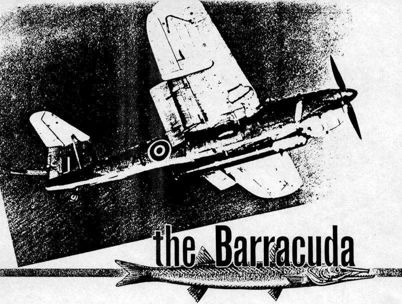
IN A dramatic carrier launched assault early last spring, the Fairey Barracuda was introduced to the Nazis. Sweeping over Alten Fjord, Norway, at the very moment when the capital battlewagon Tirpitz was about to leave her anchorage to steam away, forty-two Barracudas scored twenty-four direct hits, delivering the knockout blow to keep her down for the count.Built to most difficult specifications of the Fleet Air Arm, the Barracuda is said to be equally suited for dive, torpedo and precision bombing. As such it carries a torpedo, bombs or a mine, and contains a full set of navigational equipment as well as defensive armament. For offensive and defensive reasons it was conceived to be reasonably fast, but at the same time takeoff run and landing speed were kept at a minimum because of carrier operations. That the craft is capable of performing its duties is reflected in the large number of Barracudas that have been delivered to the Royal Navy.
External observation of the ship reveals a number of unusual features. Readily apparent are the large novel flaps which hang below the wing trailing edge. These pivot about their lateral axis and are set level for cruising, lowered slightly for takeoff, fully depressed for landing and set negatively for dive bombing. Outstanding virtue of this type flap is that it does not alter the trim of the airplane.
However, when the flaps are set at a negative angle for braking, the flow of air towards the tail is greatly disturbed. This unquestionably dictated the high-set, strutted tail plane, for it is mounted Westland Whirlwind fashion almost at the top of the fin.
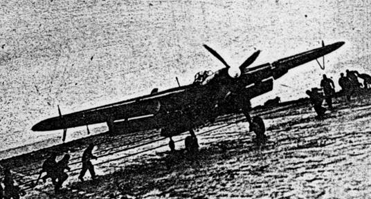
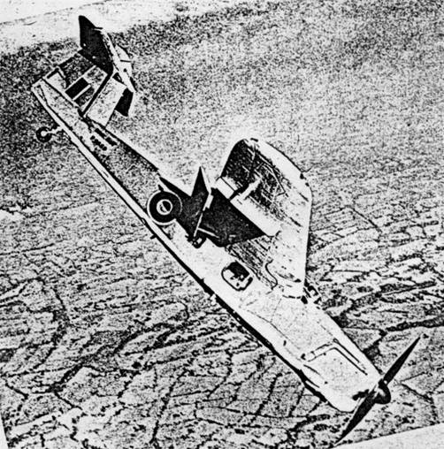
Other noteworthy features are the unique retractable undercarriage and folding wings. The problem of stowing the landing gear on a high wing ship is nicely solved by placing the unit pivot at the junction to the fuselage. In this manner the wheels arc into wells in the wing where they are stowed without a break in the airfoil's contour. Likewise, ingenuity is reflected in the manner in which the wings are folded. First, the whole trailing edge, flap included, lifts up to rest upside down on the wings' top surface, Then the wings fold back where they are secured near the tail. This collapsibility enables the craft to be stored below decks.
Because of the plane's interesting design, it makes an attractive, practical flying model. Very little deviation from scale was required to adapt the craft for a model of simple construction and maximum flight capabilities.
Plans are full scale and the following brief description outlines the manner of construction. It is suggested that the various parts be assembled right over them for greater accuracy and simplicity.
Since balsa wood is available to most builders, it is recommended for use in this project; however, in the event that white pine or spruce must be substituted, it will not handicap the model's flying efficiency too much. Simply reduce the cross-section sizes of the parts a bit and the weight and strength will remain about the same. Colorless, quick drying cement is used for adhesive regardless of what type wood is employed.
Construction of the fuselage is a good start for the project, and since bulkheads and keels are used, it is easy to make a neat, accurate job. Cut the bulkheads and four keels (top, bottom and two sides) from hard 1/16" sheet; only those notches indicated are cut out of the bulkheads, others being marked to be cut later. To assemble these parts, first pin the top and bottom keels in place over the top view, then fit bulkhead halves in place and attach the side keel. Once this structure is dry, remove It from the jig and add the remaining bulkheads and keel. Stringers are 1/16" sq. stock. Attach those closest to the side keels first, cutting the notches as the work proceeds. By placing stringers in similar positions on each side at the same time, the frame will not become disaligned.
Several other items are now added to the fuselage structure. The nose block is shaped from laminations of 1/4" sheet and the center is cut out to receive the nose plug. A removable bamboo pin holds the rubber motor in the rear and this pin is cradled by small sections of very hard balsa cemented between the stringers as shown. Rib-like formers to which the wing panels are butted are cut from hard 1/16" sheet and they must be cemented to the bulkheads and side keels at the exact position shown.
Details of the landing gear are shown on the plan and it will be found that this undercarriage is both practical and easy to make. Music wire, .040 diam., is bent as indicated and then secured to bulkhead "D" by thread which is sewed right through the wood and about the wire. Thread wrappings and the adjacent structure are thoroughly covered with cement for greater strength. External "appearance" details of the landing gear are added later.
Because the horizontal stabilizer is mounted on the rudder, the latter must be made extremely accurate and strong. Work right over the plan and assemble the rudder from 3/32" thick stock of the width shown (outlines are of odd widths, so simply cut them from sheet stock). Ribs are streamline in cross section and this is achieved by cementing 1/16" x 3/32" strips to each side of each rib. These are later cut to the streamline shape shown by the perspective. The stabilizer is one piece and constructed in a similar manner, only difference being that 1/16" material is used throughout.
Only the left wing plan is shown because of limited space. Ribs, with the exception of No. 1, are 1/32" sheet; two of each are required. Likewise spars and leading edges are cut from sheet stock. Since they are tapered, depth of each is determined by the size of notches in the ribs. Tips are cut from 1/8" sheet. Assemble parts over the plans, using pins to hold them in place until the cement hardens.
Flaps are made in an identical manner. Ribs are all identical to the one shown except for a slight variation in length.
In the event a hard balsa block cannot be obtained for the propeller, use soft white pine. Cut out the blank as shown minus the spinner and then carve an efficient right hand prop. The spinner is shaped from a separate block and fitted over the hub after the prop shaft is attached.
The removable nose plug consists of a plywood disk to which laminated squares of balsa are attached. This is shown in perspective on the drawing and is made to fit the nose block. Cement washers to both front and rear of the plug so the wire shaft which passes through it will turn freely.
Music wire .040 thick is used for the propeller shaft. Be sure to place the several small washers between the nose plug and propeller when they are placed on the shaft.
Colored tissue is used for covering, and if the job is neatly done an attractive model will result. Use banana oil or light dope for attaching the paper to the frames, which are covered before they are assembled. Numerous small sections of tissue neatly lapped are used to cover rounded areas such as the fuselage and wing tips. The whole covering may be tightened by lightly spraying with water, but clear dope should not be brushed on until the parts are assembled.
The various parts are assembled accurately to insure a good flying model. Now that the fuselage is covered, the landing gear should be completed. The vertical legs of the gear are covered with rubber tubing (such as is found on insulated electrical wire), then the covers "Y" and "Z" are cut from sheet balsa of appropriate thickness; these are cemented to the wire. It is best if part "Y" is not attached to the fuselage; thus the gear will be free to spring and absorb shock. Strut "X" is for scale appearance only and can be cemented lightly in place. Wheels may be purchased or made by hand from balsa scraps. Once painted, they are held to the axle by a drop of solder. Fit the wings in place exactly as shown (flat bottom of rib parallel to the side keel); tips elevated 1-1/4" for the proper dihedral. Rudder and stabilizer are likewise cemented fast at the exact angles indicated. Method of mounting the flaps by streamline balsa hangars is illustrated; be sure they are at 0 degrees incidence relative to the wing.
Minor remaining details are added to complete construction. The rather large cockpit canopy consists of thin celluloid sections which are cemented neatly in place. Structural details of the wind screen are represented by thin strips of black tissue which are doped to the celluloid. Undercarriage wells in the fuselage side and wing bottom as well as control surface outlines are effectively imitated by black tissue. One or two coats of thin dope are now brushed on the covering to tighten and strengthen it. Exhausts, air scoops, tail wheel and the like are made from balsa scraps. Other details found on photos of the real ship may be added according to the ambition and ability of the builder.
Now that the little ship is completed, a rubber motor is needed for power. Depending on the ship's weight, eight or ten strands of 1/8" flat rubber will be needed it should be lubricated. Hook the rubber to the shaft, then drop the loops into the fuselage, where they are to be held by a removable bamboo pin.
Much of any model's flying success results from the builder's ability to get the maximum performance from his handiwork. First, roughly adjust the center of gravity by balancing the ship along the spar-add ballast to the nose or tail as required to make it rest very slightly nose down. Then try some shoulder-high glides, making any readjustments in weight required to get a nice smooth descent. Power flights should require no further change in ballast but rather off setting the thrust line will correct a tendency to stall (down-thrust) or right or left thrust will adjust the circles. At first, use only a few power turns; then as flights improve increase the number, making any slight changes required.
Scanned from October 1944
Model Airplane News
![]()
![]()
![]()
![]()
[ Home ] [ Previous Plan Pages ] [ Special
Things ] [ Earl Stahl Plans ]