 |
 |
 |
 |
The Plan Page
[ Home ] [ Previous Plan Pages ]
[ Special Things ] [ Earl Stahl Plans ]
gt-hunter1@home.com
FLYING FLEET CANUCK
AS LAND OR
SEAPLANE,
THIS CANUCK FLIES EITHER WAY
by EARL STAHL
AT the close of the war many plane manufacturers turned their attention to the production of civilian aircraft in the belief that a vast new market was to be unfolded. All of the old makers of light aircraft were back with improved models, and they were joined by a number of former military plane producers who were entering the field to mass produce personal planes with their vast resources of money, experience and facilities. Events that followed are now history, for in less than a year sales slumped and what had appeared to be a gigantic market almost evaporated. A number of builders were forced into bankruptcy. A few of the former war plane producers simply suspended production after claiming to have lost millions through their ventures. Others, largely the old established personal plane builders, slowed to building their products in limited numbers. It became apparent that every family did not yet want a plane, or at least was not ready to buy one.
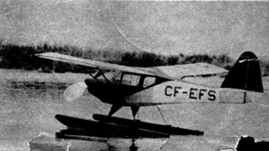
In Canada a similar. condition is apparent. Slackening customer demand has forced the suspension of production of the Fleet Canuck, our flying scale model subject for this month. Needless to say this does not reflect on the quality of this craft, which was conceived to meet the difficult conditions encountered in the all‑season flying in the north, but rather it denotes the same overproduction as compared to limited market that exists in our country.
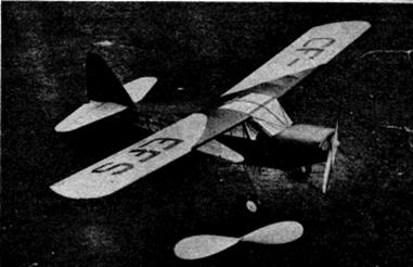
Equally adaptable to use with wheels, floats and skis, the Canuck is capable of operating from most any place a plane can. From first hand observation we can report that it is a sturdily built, comfortable ship of wide utility. It carries a good load at a respectable cruising speed of about 100 mph, and it is as easy to fly as the average American light plane. Its engine is a Continental of 85 hp.
|
|
|
|
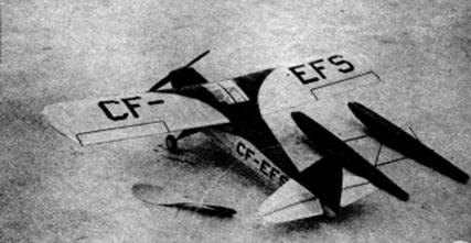
Our model Canuck is just as versatile as the real ship since it is designed for speedy conversion from wheels to floats. You who have never tried float models on neighborhood ponds and water puddles have a real treat in store, for seeing a little rubber powered ship skim across the water and then arc skyward is a refreshing change from the usual flying. There was no snow in balmy Virginia when the test ship was developed or skis would surely have been tried, too. From the standpoint of ease of construction and performance in flight this model leaves little to be desired, so on with the construction which is carried out in this manner:
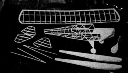
Start by building the fuselage; this consists of an underframe of 3/32" sq. strips and uprights about which formers and stringers are mounted to give the scale appearance. This underframe establishes the correct angular placement of wing to stabilizer as well as their relation to the thrust line, so reproduce it accurately. Build the two sides of the underframe, one above the other, then separate them and rejoin with 3/32" crossmembers using the top view as a guiding jig. Cut the various formers from 1/16" sheet. Stringers are 1/16" sq. strips, and it should be noted that the top one is not installed until the centersection is in place since it joins it. Cover the nose with 1/32" sheet balsa as shown by the shaded areas on the drawings. The removable nose block is made from laminations of 1/8" sheet, and it had an additional section cemented to its back to enable it to be fitted accurately into the cut‑out in bulkhead A. The carburetor intake fairing under the nose is, a solid balsa piece cemented to the cowl. Scraps of balsa are used for window outlines as well as for the balsa retainer for the bamboo dowel in the rear which serves to hold the rubber strands.
Make full size plans of the right and left wing panels and the centersection so construction can be done atop them. Using the rib pattern given, cut the airfoil sections from a sheet of 1/16" balsa that has been sanded down somewhat to reduce its weight. Tip pieces are cut from 3/16" sheet and spars are 3/32" sq. hard strips. Leading edges are 1/8" x 1/4" while the trailing edges are 1/8" x 3/8" tapered as shown. Cement all parts together; when dry, finish the edges and tips by trimming with a razor blade and sanding. Now permanently attach the finished centersection to the fuselage.
Tails come next and both stabilizer and rudder are of similar construction. Make the complete frames using 1/16" sheet for outlines and 1/16" sq. strips for ribs and spars. When the frames are dry, remove them from their jigs and add 1/16" sq. pieces to each side of each rib. These are then cut to the symmetrical airfoil shown.
To obtain fine flights from any flying scale model an efficient propeller must be used. Select a hard balsa block of the dimensions given and cut a blank to the shape indicated by front and side outlines. Drill the hole for the prop shaft and carve a right hand propeller. Carefully sand and balance the nearly finished prop, then apply several coats of clear dope to produce a smooth, hard surface. A free wheel gadget as shown in the corner of the drawing and made from a thin piece of brass or steel will enable the propeller to spin freely once the power is exhausted and thus improve the glide.
Making the two floats is an easy job. They consist of 1/32" sheet balsa sides, tops and bottoms, 1/16" sheet balsa bulkheads and solid balsa noses. To build them, first cut the top sections of each float from 1/32" sheet. This part is shown on the top view and is represented by the two innermost lines on the floats. Over the top sections erect the bulkheads in their respective positions; into the slot in each fit the 1/16" balsa keel that is shown by a broken line. Now cut the sides, the true depth of which is indicated by a lightly broken line to which the note refers on the plan. These are cemented to place, and finally the bottoms are fitted by the cut-and-try method. Carve the nose blocks from light balsa and they are finished except for covering.
Bend the landing gear and float struts from .040 dia. music wire to the shapes shown. Neatly bind front and rear landing gear struts to the fuselage using thread, and join their lower ends by soldering or by binding with thread. There is a triangle of 1/32" sheet balsa fitted between the front wires to simulate the enclosed struts of the real aircraft. The float struts may be bent at this time but they are not used until later.
Before starting to cover the frames, sand them thoroughly to remove all flaws and roughness. Colored tissue is used and numerous individual sections should be employed in covering curved sections to avoid wrinkles. We found banana oil to be the best adhesive but light dope is satisfactory. Lightly spray the covered parts with water to tighten the tissue but do not dope them until the whole model is assembled.
The various parts may now be assembled. Make paper patterns of the windshield and windows by the cut-and-try method before cutting them from thin celluloid. Then cement them to place carefully avoiding cement smears that would mar the transparency. Fit the stabilizer to the position indicated and cement it fast. Off-set the rudder a bit so the model will turn right in the glide and cement it firmly. Wings have 1-1/16" dihedral at the point shown. The wing struts are balsa strips of streamline crossection; they are shown by broken lines over the wing plan. Wheels may be purchased or can easily be made from laminations of 1/8" sheet balsa. They should have washers cemented to their sides to permit them to revolve freely.
The floats are joined by two rounded pieces of bamboo which are cemented across their top surfaces at positions shown; scale the drawings to get correct float spacing. To make the wheels and floats interchangeable, rolled paper tubes into which the wire struts fit snugly are cemented to the floats. There are four of these tubes; the two main axles are sprung together and then slipped into the front tubes. The float struts fit in the rear tubes and the tops of these wires are sprung apart, to fit into holes in small washers or bushings which have been cemented to the lower fuselage, as shown. Use of this very simple method makes possible the change from a land to water plane in a matter of minutes.
Now that everything is assembled, several costs of clear dope may be brushed on the entire model, and it would be well to apply at least two additional coats to the floats. We have found zinc stearate to be one of the best possible waterproofing mediums, and if you expect to do extensive hydro flying with your Canuck you should investigate the possibilities of this substance.
Items of detail always make a model much more realistic. Cowl openings, control surface outlines, doors, license numbers, etc. are easily represented by contrasting tissue and they go a long way towards improving the model. Needless to say, all exposed wood parts should be colored with paint or dope.
Bend the propeller shaft from .040 dia. music wire. Slip the nose plug, several washers and the propeller on in that order. Then bend the front end to suit the free wheeler being used, and at the same time make a loop into which a mechanical winder can be hooked.
The amount of power required will vary with models but 8 to 10 strands of 1/8" flat brown rubber should be about right. Lubricate the strands with a rubber lubricant (tincture of green soap and glycerine) and then attach to the prop shaft. Drop the other ends through the fuselage and slip the bamboo pin through the loops. It may be necessary to remove a small section of tissue under the stabilizer to accomplish this.
Your Canuck should balance at about the quarter chord (from leading edge) position when suspended by the fingertips. Add weight if necessary to attain this condition since only very minor adjustments are made by warping the surfaces. Glide the model over deep grass making any further weight adjustment to get a good glide.
Power flight adjustments are made by off-setting the thrust line. Start with just a few turns‑then use more power as flights improve. Placing a sliver of wood between the top of the nose block and nose, tilting the thrust line down, will aid in ironing out a stall, while right or left thrust achieved by putting the sliver at the side will reduce the power circles.
When using floats, set the model gently on the water's surface being careful not to douse the pontoons because that adds weight and may interfere with takeoffs. Quarter the model into the wind so it will turn into its natural direction and be right into the breeze as it gets under way. In helping it along, thrust it gently and it should skim along for a short distance before easing free of the surface. Incidentally, when changing from floats to wheels and vice versa, the center of ‑gravity will be changed too, so it must be corrected by reballasting.
For really long flights use a mechanical winder. Hook it to the loop in the prop shaft and stretch the rubber out the nose about three times normal length before starting to store up power.
The Canuck is a trim little ship, light in weight (ours weighs 1.7 oz. with wheels, 2.1 oz. with floats) and graceful in flight. You will find that it is as much at home on land, water and in the air as a gull.
Scanned from March 1948
Model Airplane News
![]()
![]()
[ Home ] [ Previous Plan Pages ] [ Special
Things ] [ Earl Stahl Plans ]