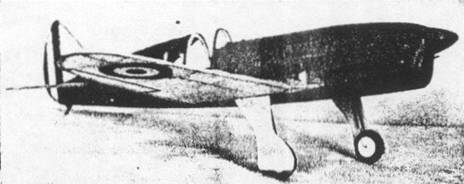
The finished Iow‑wing model; just like the "big" ship
The Plan Page
[ Home ] [ Previous Plan Pages ]
[ Special Things ] [ Earl Stahl Plans ]
gt-hunter1@home.com
The finished Iow‑wing model; just like the "big"
ship
Build and Fly
THE CAUDRON
War Plane
By EARL STAHL
An Exact Scale Model of One of France's Latest Fighters That Combines Realistic Appearance With Fine Performance
WAR has again come to Europe and as in the last great conflict, the airplane is destined to play a major hand in this ghastly game of destruction. Production of all types of planes has been speeded to a dizzy pace and unknown numbers of new designs are being developed for the purpose of destroying lives and property.
In France the Caudron firm has just recently produced a new lightweight pursuit plane, which is most remarkable. Applying the knowledge gleaned from its numerous racing planes, the most famous of which is the winner of the 1936 Thompson Trophy race, a high performance, low cost fighter has been developed. The model C-371, known as the "Cyclone" is an all wood low-wing monoplane powered with an inverted twelve cylinder Renault engine which develops 450 horsepower. And it seems that the Cauldron engineers have not forgot the formula for getting high speed with low power, since the maximum speed with full load is over 300 miles per hour. Most unusual is the fact that the wing's 29 foot is only one foot more than the overall length. That this plane will see much service at the "front" seems assured since reports, indicate that it is comparatively easy to fly - just the thing for pilots hastily trained in war - time schools.
Our model is a faithful reproduction of the real plane - and it seems to inherit some of its speed, too. Because of its attractive appearance and flight ability, it will be a worthy addition to your fleet. However, a word of caution before beginning the construction: For maximum flight performance it is necessary to make the model as light as possible while still retaining the required strength, so select all materials carefully. Firmly fix the method of construction in mind before starting to work and, finally, make the structure as accurate as possible.
 Details give it fine appearance |
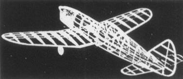 The frame is light but strong |
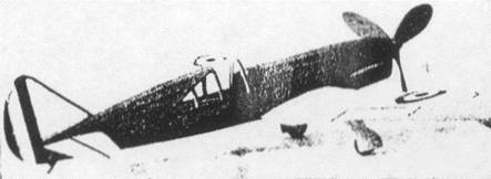 A three-bladed propeller, though small, gives fine traction |
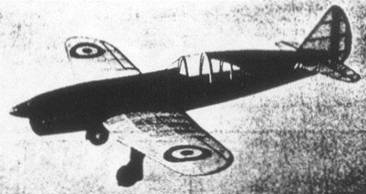
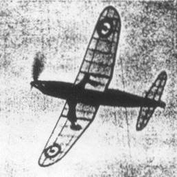 The model in full flight |
Wing
Start the construction by cutting the wing ribs from sheet balsa. Two ribs of each type are needed with the exception of R-1 of which eight are required. Two of the R-1 ribs are cut from 1/16" sheet, and all others are cut from 1/32" sheet balsa. Sandpaper all the ribs smooth and cut the notches for the spars. The wing is built in three individual pieces: the center section and the right and left panels. Make a complete center section plan and build directly atop it, using very hard spars in this unit since they must carry the shock of landings. Taper the outer trailing edges as noted on the plan. Spars of the outer wings are medium - grade wood. Trace the wing tip pieces on 3/32" sheet and cut out. Complete the wing by trimming the tips and leading edges, finally sandpapering lightly.
Fuselage
A rectangular frame forms the base of the fuselage structure. 3/32" square medium - grade strips are used to make this frame, which is shown lightly shaded on the plan. Build the two sides first, one over the other so they will be identical and then join them together with 3/32" square cross pieces as shown by the top view.
The fuselage formers are cut from 1/16" thick sheet, and in the interest of greater strength it would be best if they were cut from a sheet of laminated balsa with the grain crossed. Accurately mark the position of the notches, but don't cut them out until it is certain that the stringers won't be pulled from their natural positions. Cement the formers in place and add the 1/16" square stringers. The one stringer running back on each side is cemented directly to the underframe. Since the top cross - pieces of the basic frame will interfere with the rubber motor; it will be necessary to remove them at this time. Use a razor - blade and cut each cross - piece off flush with the inner edge of each former.
The entire nose, forward of the leading edge of the wing, is covered with sheet balsa. Because of it's somewhat difficult shape it will be necessary to use numerous strips of soft 1/32" balsa for this job. Start at the top and plank the nose carefully: cementing the covering to all of the adjacent frame. Naturally the junction between, each strip should be cemented neatly but thoroughly. Several rubber bands and plenty of pins will aid in keeping the covering in place until dry. Make the front nose block from medium balsa and accurately cut the square hole that accommodates the nose plug. Cement the block into place and carefully cut and send its shape to blend with the contours of the sheet - covered nose. Sand the nose, too, so it can be smoothly covered with paper,
As an alternate method of making the nose, a solid block of balsa can be carved to shape and then split in the center to permit its being hollowed out. Take your pick - we like the sheet-covered method best.
The wing's center section is now assembled to the fuselage. To do this it will be necessary to temporarily remove several of the vertical members of the fuselage. Slip the center section into place; the bottom spar should rest against the main longerons, and the trailing edge is lowered to the position noted on the plan. Do this carefully since the wing's correct incidence depends on your accuracy. Solidly cement the unit in place and replace the vertical members to their original positions.
The landing gear is made from .034 music wire. A full‑size layout is provided so little difficulty should be experienced. Notice that the one piece of wire is bent to take side forces while the other runs parallel to the wing rib (see side view) to absorb force and aft shock. Polish the wire with fine snadpaper to aid in making a neat soldering job. Use just a bit of soldering flux and neatly join the two pieces into one unit. With strong silk thread bind the one wire to the lower spar and with a needle sew right through the rib and about the spar to fasten the other wire. Apply several coats of cement, add the 1/16" thick triangular gussets, and your Caudron will take the roughest of landings.
Tall Surfaces
Since movable controls are of little or no value to a flying scale model they have been eliminated. The long tail moment arm will make light tall surface construction imperative. The rudder and stabilizer are made in a similar way and the entire stabilizer is made in one piece for added strength. Make the tail parts, first of 1/16" sheet outlines and 1/16" square spars and ribs, and when dry, cement additional strips on both sides to form the streamline shape. Despite the lightweight of these parts they won't warp readily.
Propeller
A semi-scale three-bladed propeller pulls our "Cyclone". The blank is shown one-half size on the plan and three are needed. Join the blanks together, as detailed, before starting to carve the blades. Finish the back surfaces first and then reduce the blades to the proper thickness by carefully cutting away the front of the blanks. Round the tips neatly. The spinner is cut in such a manner as to reinforce the hub. Being so large, it will be easy to add a freewheel device, if the cap of the spinner is hollowed out somewhat. Polish the blades to a smooth finish by applying several coats of clear dope; sandpapering lightly between each coat.
The nose plug is made to fit the hole in the nose block. Cut the front disk from 1/32" birch plywood - it can be obtained at most any model supply house. The back part is hard balsa. Drill a small hole through the center and cement washers to both sides so the propeller shaft will turn smoothly.
Bend a prop shaft from .040 wire. Place several washers between the nose plug and propeller. Imbed the front end of the shaft in the prop and glue well, or if a freewheeler is used bend the wire accordingly. Cement the spinner cap in place and the unit will be complete except for coloring.
Covering
To properly prepare for a fine covering job, the whole model must be sandpapered to remove all roughness. It is best if only the members of the fuselage which run from nose to tail touch the covering, so wrap a piece of sandpaper about some round object such as a pencil, and sand all formers to a scalloped shape. Colored paper is used because it is attractive, and its use will help reduce the total weight. Our test model is colored red and yellow but the planes now fighting in France are probably camouflaged. Colors used to camouflage pursuit planes are brown, green and yellow. From thin celluloid, cut the side windows and cement them in place. Banana oil is a good adhesive with which to attach the paper. Use numerous small pieces of tissue to cover curved such as the fuselage; the nose and other sheet balsa parts are covered with the colored tissue, too. Use individual sheets for each side of the wing parts; tips require separate pieces also. It is not necessary to fasten the paper to all of the structure - attach the outer edges only. With an atomizer lightly spray water on to all the covering, pinning the wing and tail surfaces to a flat surface to guard against warping. Our pursuit is now ready for final assembly.
Assembly
With the aid of cans, bottles, etc., block the fuselage into flight position so the plane can be assembled accurately. To insert the stabilizer in place it will be necessary to cut the tail post and former number 10, so they can be sprung apart. Once the stabilizer is correctly placed they are recemented to their original positions. Offset the rudder slightly to counteract torque. Block the wing tips up to 1-1/2" dihedral will be had; double checking to ascertain that the incidence of both outer panels is exactly the same, and then cement the wings fast. Wheels should be of hard wood since the added weight will aid in making flights more stable. Cement bearings to the wheels so they will revolve smoothly. The landing gear forks will spring apart far enough to admit the wheels. One or two coats of light dope are brushed on the whole model - do this in a dry room to keep the dope from blushing. Color dope the wheels, propeller, etc. and cement the windshield in place. The addition of the usual French insignia, control surface outlines, exhausts, etc., is really worth the time and effort consumed, for these minor details really "make the model". The wing cocardes and the rudder strips can easily be made from colored tissue, or they can be painted on with colored dope. Thin strips of black tissue effectively represent the control surface - some builders prefer to mark the surfaces with a ruling pen filled with India ink. Exhaust ports, wheel wells and other details are represented by black paper.
Depending on the finished weight of your "Cyclone" a six or eight - strand rubber motor will be needed. Attach the strands to the prop shaft and drop the other end through the fuselage with the aid of a weighted string. As indicated, a round bamboo pin holds the motor in the back.
Flying
Probably the most important single factor in obtaining fine flights from any flying scale model is patience. A well-built model, if properly handled, will provide numerous realistic flights with little or no damage to the model itself. It is important that the models glide is reasonably good before any power flights are attempted; select tall, soft grass for these tests to prevent any damage. In all probability your "Cyclone" will glide rather smoothly, but a bit of weight in the nose may be needed to correct a tendency to stall. Try a few power turns once the glide is okay; minor adjustments may be made by slightly warping a wing tip or the stabilizer, as the case may be, but correction of serious misadjustments should be made at the nose plug. Right or left thrust will control the size of the circle while under power and slight down-thrust will iron out a stall - low - wing models seldom need the latter adjustment, however. A mechanical winder is used for maximum flight performance. Our test model proved to be a speedy flyer and it was adjusted to fly in large left circles. Here's wishing you a lot of success.
Scanned
from April 1940
Model Airplane News
![]()
![]()
![]()
![]()
[ Home ] [ Previous Plan Pages ] [ Special
Things ] [ Earl Stahl Plans ]