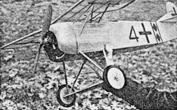
 It is of contest type, though a scale model |
 A perfect high‑performing miniature of the full‑scale plane |
The Plan Page
[ Home ] [ Previous Plan Pages ]
[ Special Things ] [ Earl Stahl Plans ]
gt-hunter1@home.com
It is of contest type, though a scale model |
A perfect high‑performing miniature of the full‑scale plane |
FOKKER D-8
Flies Again
A Realistic Gas
Model of a Famous World War
Fighter That Performs Like a Contest Plane
By EARL STAHL
PART 1
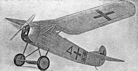
 The engine is neatly cowled |
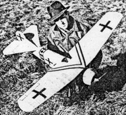 The author with completed model, ready for a flight |
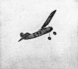
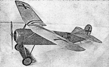
The climb is fast and steep
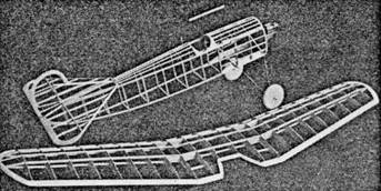 The uncovered framework shows strength and simplicity |
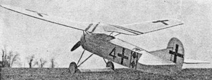 Carefully detailed, it closely resembles the full‑scale plane |
DURING the closing weeks of the first World War there appeared over the front lines a nimble little monoplane that is generally credited as being the finest fighter of its day. This was the famous Fokker D-8 of the German Imperial Air Force. Powered by a rotary Oberursel engine of 110 horsepower, the D-8 had a speed of 115 m.p.h. It climbed at a rate of 1,500 ft per min. and could ascend over four miles. In the ability to maneuver and dive it was unexcelled. So superior was the performance of this ship that it would have been a tremendous blow to tile Allied air forces had any, great number been completed before the war's end.
In selecting a design for a flying scale gas model one call scarcely find a better subject than the Fokker D-8; for here is a plane with aerodynamic proportions similar to the majority of contest models. A very short nose combined with a long tail moment arm, tail surfaces of proper proportions and a parasol wing of generous size, all contribute to the model's stability. In construction the D-8 is extremely simple and practical and anyone who has built rubber or gas models with success should experience little difficulty in duplicating it.
Our model Fokker D-8 was designed to fly successfully with any Class B engine; however even the smaller Class C power plants should prove satisfactory. The wing span is 57" and the weight with intermediate size batteries is 28 ounces. This makes the wing loading about eight and one-half ounces per sq. ft. An inverted Ohlsson "23" swinging a 12" propeller was used to power the original model.
How does it fly? Well, test flights were conducted high in the snow covered mountains of Pennsylvania with the temperature uncomfortably below freezing. With the regular 20 second engine run, flights of one and one-half minutes were made, which is certainly not bad for a scale model. Entirely unassisted the little ship lifts from the runway after a short run and eases into a fast circling climb. Under power the circles are to the left and at the top of the climb it "rolls out" into a flat, level glide to the right. Under more favorable flying conditions it should give an even better account of itself, since it attains enough altitude to take full advantage of rising currents.
Before construction can be started, it will be necessary to enlarge some of the plans to full size; with the exception of the full size fuselage formers and wing ribs most parts are shown one-third full scale. Obtain a large sheet of ordinary wrapping paper and "scale up" the plans to actual size. A pair of draftsmen's dividers will simplify the task since it will only require "stepping off" each dimension three times. When duplicating the side view of the fuselage, the top line of the upper longeron should be used as the reference line since it is straight. In duplicating curved parts such as the rudder, draw squares of the indicated size and then draw the curved line through the corresponding positions. Now for the actual construction.
Fuselage
The fuselage is of standard construction. Build two side frames using ROCK HARD 3/16" sq. balsa for the longerons and cross pieces. Build one side atop the other to insure that they will be identical. When the sides are dry, remove them from the plan and turn them up side down over the top view. Pin them the proper distance apart and cement cross pieces to place, being careful to keep the whole structure lined up evenly.
Fuselage formers come next. Make complete paper patterns of each and then cut them from 1/8" sheet balsa. Two each of formers 1S, 2S and 3S are required. Cement the formers to their respective places. The fairing strips are medium grade 1/8" sq. balsa. It will be noted that many of the formers lack notches so when this is the case, the fairings are cemented directly to the sides as shown. The cockpit is made of 1/16" sheet. Cement several sheets together so the stock will be wide enough and then cut out the center to the shape indicated. The cockpit piece is then fitted accurately into the space between formers No. 4 and No. 5 and cemented fast.
The tapering strips that give the stabilizer its correct incidence are shown on the plan. They are 3/16" wide and taper from 3/32" to zero. Two are required and they are glued to the fuselage with the 3/32" end at the rear.
Landing Gear
Landing gear struts are formed to the size and shape shown. 3/32" diameter music wire is used for the front strut while 1/16" diameter wire is used for the rear. A vise is very helpful for bending the wire but heavy pliers can be used if necessary. Bend the struts accurately and note how the rear one is bent to join with the front.
The struts are solidly attached to the fuselage structure, the spring of the wire being sufficient to absorb the shock of landings. Use strong thread or light twine for the purpose of binding the struts to the cross pieces and longerons, and then apply several coats of cement. The 3/16" sq. diagonal ones shown on the plan are cemented to place once the landing gear is attached. Join the two landing struts with solder. Two No. F-1 reinforcements are cut from extremely hard 1/8" sheet balsa; cut the several notches so they will fit accurately over the cross members of the fuselage and landing gear wires. Cement these to the bottom longerons and uprights to strengthen the fuselage.
Fairings on the landing gear struts are simply soft strips of 1/16" sheet balsa, attached to the wire by strips of tissue wrapped spirally around both. These should not be attached until the fuselage is covered, however.
Because of the unusual size and shape of the wheels it will be necessary to make each of them from three discs of very hard 1/4" sheet balsa that have been laminated together. If the builder has access to a lathe it will help, but the wheels can be shaped accurately with a sharp knife and some sandpaper. Bushings of some sort must be used to permit free and accurate turning. If the wheels are covered with silk they will be greatly strengthened.
Wing Mount
While construction of the wing mount is not difficult, it must be made with the greatest of accuracy. The three cabane struts are shown in detail and all are made from 1/16" diameter music wire. Make accurate full size sketches of each strut and then use them for patterns to aid in shaping. Note the side view of each strut to determine how the ends are bent. Attach the front and center members to their respective positions on the fuselage; strong thread is used to attach them to the longerons. Ends are adjusted to meet accurately and then they are soldered together.
Attach the rear struts. Next select two pieces of 1/4" sq. white pine for the wing rests; neatly attach the pine pieces to the struts with thread wrappings. Once the wing rests are in place they should be checked for correct incidence. If the top of each pine strip is exactly parallel to the top fuselage longeron, it is correct; but if it is not, it must be removed and the proper adjustment made to make it exactly right. This is very important. Apply several coats of cement to all thread bindings and joints once the wing mount is properly aligned.
As shown on the side plan, triangular shaped reinforcements are used to strengthen the upper longeron at the wing mount. Cut these gussets from medium grade 1/8" sheet balsa and then cement them to place at stations No. 1 and No. 3. To strengthen the fairing strips to which the false struts are later lightly attached, it will be necessary to glue triangular shaped 1/8" thick strengtheners to the back of the first bulkhead as shown on the pattern for the fuselage formers. After the wing is completed the tops of the wing rests are fitted with pieces of balsa strip so they will conform to the curvature of the wing's under surface. The cabane strut fairings, small blocks to prevent wing sliding, false struts, etc., are completed later.
Engine Unit
A removable engine unit is featured. Obtain a 6" x 6" piece of 1/8" birch plywood for the engine bulkhead; it should be free from warps. Half the full size bulkhead is shown on the plan. Use a jig saw to cut the piece to shape. As shown by broken lines on the plan, 3/16" sq. strips of balsa are fitted to the back so the bulkhead will fit snugly to the fuselage front.
Aluminum motor mounts are used. A pattern is given which will enable the builder to bend them from 1/32" sheet aluminum. Most of the model supply houses carry mounts that will prove satisfactory. These should, however, be modified so the front mounting hole will be 2-5/16" from the back.
Several of the mounting holes are shown on the engine bulkhead pattern. The position of these holes is correct for all inverted Ohlsson "23," but if you expect to use any other engine or mount the Ohlsson upright, the location of the various holes must be changed. The important thing to remember is to keep the line of thrust exactly where it is shown on the plan.
Because of the very short cowling it is necessary to mount the engine close to the fire wall. For this reason a hole must be made in the bulkhead into which the intake tube call be fitted. Naturally this makes it impossible to choke the engine as usual; on the original model we simply primed it through the exhaust port with an eye dropper and this method proved to be quite satisfactory. Depending on the engine used, it may be necessary to fit a piece of rubber tubing over the intake and then extend it out the fuselage side to facilitate operation.
With the exception of the first few glides and power flights, a cowling has been used at all times. The engine runs well within the cowl and it keeps the oil off the ship. Without it the model loses its snappy appearance and it seems to fly better when the cover is in place. An aluminum cowling is used on the plane shown in the photos and after many flights it remained undamaged and in excellent condition. This was made from a 5-1/2" diameter aluminum cowl as stocked by the model supply houses. The bottom was split and the metal was stretched enough to make it fit to the engine bulkhead. Then, using shears, the bottom edges were trimmed to shape as indicated.
Those who desire to make their own cowling can build one from laminated balsa discs, or possibly a plastic cowl as described in an article in the September 1940 issue of MODEL AIRPLANE NEWS will appeal to the builder.
Use of a cowling will naturally require that extensions be added to the needle valve, gas tank and possibly the spark control. Depending on the engine used, these items must be worked out to suit each individual case. Four small hooks bent from .040 music wire are cemented to the front of the engine bulkhead so rubber bands call be wrapped about them and the wing and landing gear struts to hold the engine unit in place.
The concluding installment for building the Fokker D-8 will be published next month.
Scanned
from June, 1941
Model Airplane News
![]()
![]()
![]()
[ Home ] [ Previous Plan Pages ] [ Special
Things ] [ Earl Stahl Plans ]