The Plan Page
[ Home ] [ Previous Plan Pages ]
[ Special Things ] [ Earl Stahl Plans ]
gt-hunter1@home.com
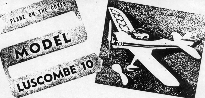
By EARL STAHL
Build a flying scale model of this little
sport plane that looks like a pursuit job
Recent months have shown a revival in investigating potentialities of single seat sport planes, but whether or not they are to take their place in popularity beside the two and more place civilian models is still a matter of speculation. In the late twenties and early thirties a number of one place planes were buzzing around airports. These included the Buhl Bull Pup, several types of Heaths, Corben Baby Ace and Super Ace, Knight Twister and numerous others. The mushrooming popularity of Cubs, Aeroncas and Taylorcrafts soon, however, shoved these craft into the background and not until now has new interest been shown in them.
Several manufacturers are again looking to one place planes and the result of their investigations of performance possibilities and market potentialities may result in assembly lines for their production. Luscombe's experimental single seater is one of the most promising to be shown to the public. Using a regular 65hp Continental engine, it is reported to have a cruising speed of more than 120 mph.... and that is really something! A plane of this type would be especially desirable for cross-country piloting because it would provide rapid transportation at very low cost. This model 10 was fabricated largely from standard Silvaire parts which means that it surely inherits the durability and utility of this popular sport plane. How the little ship flies is not known for to our knowledge only the Luscombe test pilots have flown it, but if it bears the fine flight characteristics of the Silvaire it will be more than satisfactory for the author, who owned one of the latter and considers them "tops".
As a model the Luscombe 10 provided one of the sharpest looking yet easiest built planes we have ever designed for Model Airplane News. No deviation from scale was required to adapt the proportions to a satisfactory flying model design. Build this little ship and you will have one that you will be proud to display and fly.
The drawings and text are for a rubber powered model, but by doubling the plans and altering the structure slightly to provide for the motor a fine control line model can be had. As usual we caution you to work carefully with the best materials because the finished product can be no better than the effort and raw materials put into it. Medium weight balsa is used throughout for the rubber model while a gas job should be fabricated with harder grade, particularly for spars and such. Regular colorless, quick-drying cement is used to assemble the various parts.
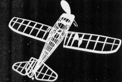
Since they are most simple, lets start with the tail surfaces. Join the drawings of the rudder and make a complete drawing of the stabilizer so assembly can be accomplished right over them. Incidentally, notice that the stabilizer is made in one piece: also that both units are of identical rib construction. Cut the outlines from 1/16" thick balsa and make the spars and ribs from 1/16" sq. strips. When these structured are built, remove them from their jigs and cement strips of soft 1/16" sq. to either side of each rib only. Then cut these overlaying strips to the streamline rib shape. This type of construction is the lightest and strongest we know for small models.
To start wing construction, make a right wing plan by tracing the left plan with carbon paper reversed. Cut ribs, spars and leading edges from materials specified. Assemble the parts over the plans, building the wing into two halves and leaving rib No. 1 off until the halves are assembled. Join the halves with 1-5/16" dihedral at each tip and then install rib No.1. Trim and sand the edges and tips to their proper shapes to complete the structure.
Since the landing gear is part of the wing unit, it should be made now. Bend the .040 music wire as shown to form a right and left strut. Bind and sew these right to the wing as illustrated, then cement the area for added strength. Wheels are made from laminations of sheet balsa and they should have bearings to permit them to revolve freely. Wheel pants and fairing struts are likewise laminations of sheet balsa. Note that centers of the pants are cut out for the wheels while centers of the struts are open to allow the wire struts to spring and thus absorb shock. Incidentally, don't attach these landing gear details until the wing has been covered.
For years we have been modeling monocoque fuselages in the manner described here. This method calls for the use of four sheet balsa keels to give the proper outline shape, bulkheads to form the crossection, and fairing stringers: it is both easy to accomplish and strong so we recommend it highly. Go about the construction in this manner: Trace top and bottom outlines of the side view as well as sides of the top view to get the shapes of the keels which are cut from 1/16" sheet. Bulkheads are likewise 1/16" sheet and two of each are needed as they are made in halves. To assemble, pin top and bottom keels over the side view: note how the top keel at the rear forms the mount for the stabilizer and how the bottom keel below the cockpit is curved to fit the top chamber of the wing rib. By making these very accurately, assembly of the parts is made easy and exact.
Over the side view, place half of the bulkheads in their respective positions, then slip a side keel into the notches. Now pick this frame up and add the remaining formers and keel. Stringers of 1/16" sq. stock are next attached to place. Add those closest to the side keels first, placing one on each side at the same time to avoid pulling the structure out of line. Incidentally, it will be necessary to cut some of the notches in the bulkheads as assembly progresses. We do this to assure perfectly straight stringers and it makes the task no more difficult if a razor blade broken to a sharp point is used. On the lower fuselage between bulkheads B and C curved pieces of 3/32" sheet are attached to fit to the wing's uppercamber. Just aft of bulkhead F small inserts of 3/32" sheet are installed at each side to retain the bamboo pin that holds the rubber motor. The nose section may be made entirely from laminations of cross grained sheet or it may be made from a block - or several small blocks glued together to make a large one - with the 1/2" thick laminated front shown. Check the drawings for details and note how the whole nose is hollowed for lightness. In the extreme front laminated portion of the nose, a square hole is cut to receive the removable nose plug which is shown. Carve the outside of the nose to shape, using pictures of the model and real craft as a guide.
Two propellers are shown; the scale one which we made from thin laminations of white pine and mahogany and the enlarged flying one for real performance on the flying field. Carving a good flying prop is of such importance that much care must be exercised. First cut the blank which is a hard balsa block to the size and shape given. Drill the tiny hole for the propeller shaft and then begin to carve. A right revolving prop is required and it is best to finish the back face of the blades first. Cut and sand about 1/16" undercamber into the back, then cut away the front until the blades are of the required thickness. Round the blades and sand them into balance.
The nose plug is simply squares of 1/8" thick balsa glued together with a 1/32" thick plywood face. Cement washers or bearings to the plug to fix the line of thrust.
To assemble the propeller unit first bend a shaft from .040" music wire. Slip the nose plug, several washers and the propeller on the in that order. Bend the end of the shaft into a U and pull it back into the prop, or better still fit the propeller with a free wheel gadget and bend the end of the shaft accordingly.
With all the parts constructed they may now be prepared for covering. Carefully sand them so that as near perfect a job as possible can be done. Colored tissue is recommended because of its lightweight and attractiveness; it is stuck to the frames by banana oil or very thin dope. For the tail surfaces and bottoms of the wings use a separate piece for each flat surface, and for the tops of the wings use and additional section for the tips since they are tapered slightly. The fuselage will require numerous small pieces neatly lapped to avoid wrinkles. To tighten the tissue lightly spray it with water and allow to dry; however do not dope the tissue until the whole model is assembled.
The little model will begin to resemble the real ship now that parts are ready for assembly. Slip the wing into place and cement it fast. Make the two small fillets from 1/32" sheet balsa and attach them with glue. Now fit in any small pieces of 1/16" sq. needed to shape the bottom of the fuselage and cover the area. Slip the stabilizer into place and cement. The rudder is placed perpendicular to the stabilizer with the front offset a bit for a right turn; check the alignment of all surfaces carefully. Finish any small fillets between tail and fuselage and the covering can then be sprayed again to be sure all wrinkles are eliminated. Now brush one or two coats of light dope on the covering.
It is the minor details that "make" any model so they should not be overlooked. Probably the first part that will catch the eye of anyone viewing the model Luscombe will be the bubble canopy. The one on the original was easily made by simply heating a piece of 1/32" soft plastic in an oven and then stretching it down over a carved wood mold. Two persons (or any reader with four hands can do it himself) are needed for this job, and if at first it is not perfect simply reheat and try again. Incidentally, if strain marks appear on the canopy they can easily be eliminated by rubbing with auto rubbing compound or Simonize cleaner. Landing gear fairings, wheels and the like may be installed at this time. Details such as license numbers, control outlines, stripes, cowl grill, cockpit details, etc. are all represented very effectively by tissue of contrasting color doped to the covering. Tail wheel, Exhaust stacks and the like are made from scraps of wood. Sticklers for details can find more on photos of the real ship and they may dress up their ships to the limit of their initiative and ability.
Power required for each model will vary with the weight and general efficiency; however six or eight strands of 1/8" flat brown rubber will be about right. Lubricate the strands with a mixture of tincture of green soap and glycerin before dropping them within the fuselage. To do this hook one end of the loop of strands to the prop shaft and then tie the others together with a bit of thread and drop them through the nose. A removable bamboo pin is slipped through the back to retain them.
Little remains now but enjoyment of the fruits of the hours of labor. However, remember that to get the most of this or any model it must be handled carefully and skillfully. With this in mind select a nice grassy field and a calm day for the test flights. First tests should be glides from shoulder height. If a stall occurs, add a small amount of weight within the nose; should it dive, add weight to the tail. Once glides are okay, try a small amount of power. Observe the flights carefully, adjusting the amount of turn by putting slivers of balsa between the nose plug and nose to offset the thrust line right or left and at the top to tilt it down should the model stall while under power. As flights become more satisfactory, increase the amount of power making any further minor readjustments required. The author found that his scale models are most satisfactory when they are adjusted to fly in a large left circle when under power, and then when they start to glide the turn is large and to the right.
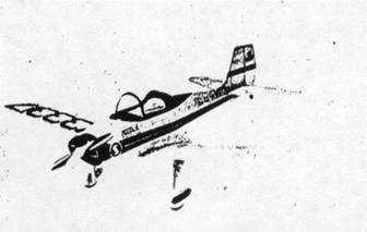
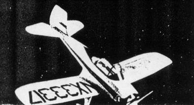
The Luscombe 10 is a smart little ship, trim in line and fleet when on the wing; you are sure to find that yours will take to the air as readily as a duck takes to water.
Scanned from September 1946
Model Airplane News
![]()
![]()
![]()
![]()
[ Home ] [ Previous Plan Pages ] [ Special
Things ] [ Earl Stahl Plans ]