
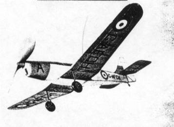
Realistic and graceful in flight as well as design, with neat super-light construction
The Plan Page
[ Home ] [ Previous Plan Pages ]
[ Special Things ] [ Earl Stahl Plans ]
gt-hunter1@home.com
BUILD AND FLY THE MILES MAGISTER
A low-wing scale model with superior
flying qualities
by Earl Stahl
Realistic and graceful in flight as well as design, with neat
super-light construction
EQUALLY important to a nation at war as the actual production of war planes is the training of crews to operate and maintain them. Throughout the British Empire a pilot force and other aviation specialists are being trained to sinew the air arm for the knockout blow against the Axis.
Many Royal Air Force cadets are now receiving their initial flying in Miles "Magister" trainers, our subject for this month's flying scale model. Strikingly similar to plans now being used by our own Army Air Corps, notably the Fairchild PT-19, the "Magister" has been engineered for the required trainer qualities of stability and strength.
Structurally the Miles Magister is all wood, following a practice popular in England for some years. The fuselage is a box structure of spruce with plywood stressed covering. Wings are in three sections, also plywood covered, and can be folded to conserve space. Instructor and student are seated in tandem; open cockpits each with a full set of instruments.
Power from a 130 hp. De Haviland Gypsy inverted, air-cooled engine gives maximum speed of 145 m.p.h.; cruising speed of 125 m.p.h. and with flaps extended lands at 45. This trainer climbs 1,200 ft. per min. to a service ceiling of 18,000 ft. Normal range is 400 miles.
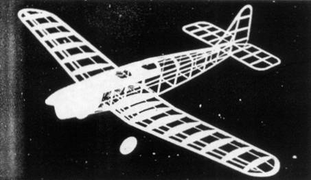
A model Miles Magister is interesting to build and fly. Extreme structural simplicity and efficient aerodynamic design combine to produce a low-wing model with flight capacity comparable to many high-wings, flying steadily with plenty of power and the appearance of a full size plane.
Before actual construction of the model, study the plans carefully to become familiar with the details. With a clear picture of each detail in mind, gather all necessary material and begin.
Fuselage
The fuselage underframe is constructed first, shown lightly shaded on the plan. Work directly over the magazine pages and make two side frames, one atop the other. Longerons and uprights are 3/32" sq. balsa. When dry, the side frames are inverted over the top view of the fuselage and the 3/32" sq. cross-pieces are cemented to place. Check frequently for alignment.
Formers are cut from medium grade 1/16" sheet balsa. Notice that several formers do not have notches for the stringers and where this is true, the stringers are attached directly to the sides, as shown. Cement the formers to the positions indicated and then add the 1/16" sq. stringers. Stringers which run back the sides are attached directly to the underframe. Because of the high thrust line, remove the middle section of the 3/32" sq. cross-pieces once the top formers are in place, to prevent interference with the rubber motor.
The shaded area of the nose is covered with soft 1/32" sheet balsa. Use the widest stock available and cement the covering to the entire adjacent frame. Pins and rubber bands are helpful to hold the sheet in place until dry. The top section from No. 3 to No. 6 is covered also. Cut this piece to fit accurately, then cut the cockpits; a pattern indicating the shape is given. Cement to place as with the nose covering. The nose block is cut from two pieces of 1/4" sheet cemented cross-grain; cut out the square hole for the nose plug, then roughly cut to shape and cement to the fuselage. When dry, cut and sand the entire nose to a smooth, attractive shape.
Tail Surfaces
Construction of the tail surfaces is easy and both the rudder and stabilizer are constructed in a similar manner. For greatest strength the stabilizer is made in one piece so make a full size plan. Outlines are cut from 1/16" sheet and the spars are 1/16" x 1/8"; ribs are 1/16" sq. strips. When dry, remove the frames from the plan and soft pieces of 1/16" sq. are cemented to both sides of the ribs; cut to a streamline shape when the cement has hardened. Trim and sand the surfaces to final shape.
Wing
The wing is made in three part; plans for the right wing and half of the center section are given. Prepare a full size plan of the left wing and whole center section so the various parts can be assembled over them. Two of each type rib with the exception of No. 1 are required; all are cut from 1/32" or 1/20" sheet. Notches for the various spars must be cut with accuracy to insure a neat job. Leading edges of the outer sections taper as shown by broken lines. Taper the trailing edges to correct cross-section before pinning them to place over the plans. Assemble the parts right over the plans using pins to hold them in place until the cement is hard. Tips cut from 3/32" sheet should be cemented to place. Trim the edges and tips to shape, finish with sandpaper and then solidly join the three units together with 2-1/8" dihedral at each tip.
Landing Gear
Landing gear struts are bent from .040 music wire, which is bent so as to join the spar provided for that purpose and rib No. 1. Be sure to make a right and left strut and then attach them to place with thread and plenty of cement. Use a needle and thread to sew right through the ribs and around the wire. Apply several coats of cement to the entire adjacent area. The rubber tubing covers are not added until the wing has been covered.
Make the wheels from laminated discs of balsa or they may be bought. Cement bearings to the sides so they revolve accurately and smoothly.
Propeller
For best performance any flying model must have an efficient propeller. Select a hard block 1" x 1-1/2" x 8-1/2" and cut the blank to the shape shown. Drill the tiny hole for the prop shaft then start to carve a right hand propeller. Finish the back surface of the blades first, then cut away the front to the desired thickness. Round the blade tips similar to the prop in the photos. Use rough and then fine sandpaper to smooth and balance the blades. The spinner is made in two individual pieces cemented to the sides of the hub. A free-wheel device should be attached to improve the glide and a bearing is cemented to the back so the prop will revolve smoothly. Apply several coats of clear dope with light sanding between each and then color dope to a nice finish.
The removable nose plug is shown. A disc of 1/32" plywood forms the front while the back is laminations of hard sheet balsa. Flight trials of the test model indicated that several degrees of both right and down thrust are desirable so this can be incorporated in the plug at this time. Fix the thrust line by cementing washers to the front and rear of the plug.
For the propeller shaft, use .040 music wire. Place several washers between the prop and nose plug before bending a loop in the end into which a winder can be hooked.
Covering
Before the frames are covered, carefully sand to remove all flaws and roughness. Either colored tissue or light grade Silkspan may be used; we like the appearance of tissue best but it requires numerous pieces on curved parts to prevent wrinkles. Cover the fuselage first with light dope or banana oil for adhesive; also the sheet balsa nose is covered with tissue. Use an individual piece to cover the top and bottom of each wing section and the tail surfaces. Spray the various parts lightly with water to tighten the covering but clear dope is not applied until the model has been assembled.
Assembly of the Miles Magister is simple. First fit the wing into the recess in the fuselage and cement firmly. If parts have been built with accuracy, the angle of incidence will automatically be correct. Finish the section from wing to fuselage with small pieces of 1/16" sq. Wing fillet shape on the original model is shown; cut a paper pattern of it to fit the model exactly before cutting two from 1/32" sheet. If the builder desires, he can cut wing root pieces from 1/16" sheet to the shape of the rear of the fillet and cement them between the fuselage and wing to support the back of the fillet, though hardly necessary. Once cemented to place the fillets are covered with colored tissue, as is the uncovered portion under the wing. The Stabilizer is attached to the top longeron at the angle shown. Off-set the rudder about 1/16" for a right turn in the glide. Check and recheck everything for correct alignment. When dry, tissue fillets are attached between the stabilizer and rudder. Moisten any covering wrinkles with water and dry before brushing one or two light coats of dope on the entire covering.
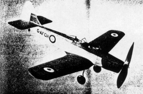
The large propeller gives long flights, while cockpit and
decorations give a realistic touch
The model can not be considered complete until numerous minor details are added. Rubber tubing of the correct diameter is slipped over the landing gear wires and then doped black. (This tubing can be obtained from any model supply house, or can be stripped from many electrical appliances.) Wheels are colored before being fastened by washers soldered to the axles. Two windshields are cut from celluloid; if thin black tissue strips are doped to the surface to represent a frame, realism is increased. Carve a headrest from soft balsa and cover with tissue to match the fuselage covering. The tail wheel, exhaust stack and similar items are made from scraps of balsa. The British insignia is found on the wings and fuselage sides of the real plane, and can be made from colored tissue. Control surface outlines, cowl openings, identification markings and similar details are made from tissue also.
Our model is powered with either six strands of 3/16" rubber or ten strands of 1/8" flat, brown rubber. Hook the motor to the propeller shaft and then drop the other end through the fuselage. It may be necessary to remove a small section of the covering in the rear to get the strands, held by the removable bamboo pin, into position. The model Miles Magister is now ready for initial flight.
Flying
The secret of obtaining fine flight from a properly designed flying scale model is simply great patience. It is indeed highly improbable that your model will fly perfectly on its first flight. Before actual tests are begun, the model should balance when held about 1/3 the wing chord; addition of a small weight to the nose or tail makes this correction. Check glide the ship, warping the back of the stabilizer down a bit to iron out a stall or warping the back up to correct steep glide. Hand launch over deep grass or weeds observing in particular the glide and making any necessary adjustments. When a good glide has been obtained, perfect powered flight by off-setting the thrust line with slivers of wood between the nose plug and nose. Increase the number of turns as flights improve. Treat the model with care until its flight characteristics are learned, then try long flights - and you can really get them with the Miles Magister.
VICTORY
Scanned
from February 1942
Model Airplane News
![]()
![]()
![]()
![]()
[ Home ] [ Previous Plan Pages ] [ Special
Things ] [ Earl Stahl Plans ]