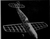
 Carefully designed for flight yet realistic in appearance |
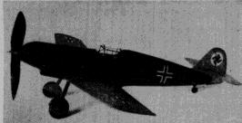 The sleek lines and large propeller give it Right efficiency |
The Plan Page
[ Home ] [ Previous Plan Pages ]
[ Special Things ] [ Earl Stahl Plans ]
|
Carefully designed for flight yet realistic in appearance |
The sleek lines and large propeller give it Right efficiency |
By EARL STAHLA Flying Messerschmitt Pursuit
FOREMOST fighting plane of Germany's potent air force is the deadly Messerschmitt Me-109, a single-place, low-wing monoplane of all-metal construction. Only the Focke-Wulf Fw-190 equals its speed, range and fire-power; and latest versions mounting rockets are considered the most deadly fighting plane of the Luftwaffe. One of the smallest of the fighter planes, it is characterized by blunt, square lines, straight wing tips and an awkwardly sprawling landing gear, all making for simplicity of mass production. In the air, however, it is a merciless, powerful foe.
The latest version is capable of more than 400 miles per hour, which compares favorably with the latest Royal Air Force and Army Air Force fighter planes teamed against it. However, one of the greatest assets of a pursuit ship, maneuverability, is apparently lacking. Reports from the "front" indicate that superior maneuverability of the British "Hurricanes" and "Spitfires" has proved to be the decisive factor in many encounters with the Messerschmitts, In France, the American-built Curtiss Hawk, while somewhat slower, was especially effective against its less maneuverable foe.
Various combinations of armament have been found on planes that were shot down Some planes have as many as eight machine guns while others employ an aerial cannon in combination with several guns. An armor protected cockpit and self-sealing fuel tanks afford a degree of protection for the pilot.
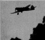
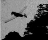
Your fleet of models will not be complete without a miniature Messerschmitt Me-109. The plans which accompany this article will enable you to construct an attractive, authentic model with a minimum of labor. Flight performance of the model shown in the photographs is remarkable for this type plane, for despite the low-wing, pursuit design, the model has made many stable, realistic flights - and it has never crashed. Standard construction methods are used throughout However, it is advisable to thoroughly study the plans and instructions before starting to build.
Fuselage
Construction is begun with the fuselage. Trace the top, bottom and side outlines of the fuselage on a sheet of paper to obtain the correct shape of the keel pieces. Lightly cement the paper patterns to a sheet of medium-grade 1/16" sheet and then use a sharp razor blade to cut them out. Bulkheads also are cut from 1/16" sheet; cut only those notches shown, others are marked but they are cut later as needed. Pin the top and bottom keel pieces over the side view and cement half of the bulkheads to their respective positions. It will be noticed that bulkhead No. 5 is cut and then recemented at the angle shown. Attach one of the side keels after making certain that the bulkheads are aligned correctly. Remove this portion of the body from the plan and place the remaining bulkheads and the other side keel. Stringers are light-grade 1/16" square strips. As the work progresses, it will be necessary to cut many of the notches for the stringers; use a razor blade that has been broken to a sharp point for this operation. Once a stringer has been attached to one side always place another in the corresponding position of the other side to avoid pulling the body out of line. Pieces of hard 1/16" sheet cemented between the stringers provide the anchorage for the bamboo pin that holds the rubber motor in the rear.
As indicated on the plan, the front portion of the fuselage is "filled-in" with pieces of very soft 1/16" sheet. Individual pieces of balsa are cut so as to fit snugly within the space between the formers and stringers. An exception is that section of the nose over which the radiator is later placed. The extreme front of the nose is shaped from four pieces of sheet that have been cemented together. As shown, the center of the nose piece is cut out to receive the nose plug. Cement this nose block to former No. 1 and when dry cut and sand the entire fuselage front to an accurate, smooth shape. Make the radiator front from 1/4" sheet: the shape is indicated on the first page of plans. Very soft 1/32" sheet is used to complete the radiator which extends back to bulkhead No. 3.
Special members to which the wings and landing gear are attached are cut from hard 1/16" sheet; two are required. They fit over the bottom keel and stringers and are cemented to the backs of formers No. 3 and No. 4. These members serve the purpose of providing a sturdy mount for the wings and landing gear and they are designed to assure the correct wing incidence and dihedral.
The wire landing gear should next be formed. To insure accuracy a full-size lay-out of the gear should be made. Note that the wheels toe out at an angle of about 5 degrees; also notice how the struts sweep forward when viewed from the side. Bend the struts from a single piece of .040 music wire; The struts are attached to the member provided for that purpose by binding with thread. Apply several coats of cement to the thread wrappings and over the wire and surrounding wood parts. A wire landing gear of this type, if carefully made, will take all of the punishment normal flying can give it. The strut covers and wheels are attached later.
|
|
|
|
Wing
Both the right and left wing panels are shown full size on the plan. 1/32" sheet is used for all of the ribs with the exception of W-1 which is cut from 1/16" thick stock; two of each are required. Cut the ribs and sand them smooth. Notches for the spars and leading edge must, be cut with accuracy to insure a neat job when completed. Assembly can be done directly over the plans. Pin the ribs to position and then cement the leading and trailing edges and the 1/16" square spars to place. Tips are made from 1/8" sheet. When dry, remove from the jig and cut and sand the edges and tips to their final shape.
Tail Surfaces
To improve the flying qualities of our model it has been necessary to increase the area of the tail surfaces. Both the stabilizer and rudder are constructed in a similar manner: A complete frame is made first, using 1/16" sheet for the outlines and 1/16" square strips for the spars and ribs.
When dry, this frame is lifted from the plan and then very soft 1/16" square strips are cemented to both sides of each rib. These pieces are cut and sanded to a streamline shape once the cement has hardened and the leading and trailing edges are sanded to blend with the streamline shape also.
Covering
To property prepare for a neat covering job the entire frame must first be sanded thoroughly to eliminate all flaws and roughness. Our original plane was colored deep blue and red with black and white trim; however, the real war planes are camouflaged. Colored tissue is best suited for this job since it is both attractive and light in weight. Cover the fuselage first; grain of the paper should run from nose to tail. Banana oil or thin dope is used to stick the tissue to the frames. Numerous small pieces of paper must be used to prevent wrinkles but the individual pieces should be lapped neatly. The nose and other wood parts should be covered with tissue also. Cover the wing and tail surfaces using a separate piece of tissue for each side of each unit; grain of paper runs spanwise. Bottom of the wing from W-1 to W-3 is not covered at present. Tips, etc., require individual pieces, too. The parts are lightly sprayed with water to tighten the tissue but they are not doped until the model has been assembled.
Assembly
The various parts are now assembled. Fit the notches of the first two ribs of each wing panel to the special wing mounts. If the structure has been made with accuracy, the incidence of each side will be exactly the same and the wing tips will be elevated to the correct dihedral. In the event that a small error is apparent, the structure can be altered slightly to obtain the desired alignment. Once the position of the wings is satisfactory, they are cemented fast. Tissue is next applied to the uncovered sections of the wings The small 1/32" sheet wing fillets, are placed in position; it is advisable to make a paper pattern fit exactly to your plane before cutting the ones from sheet balsa. Once the fillets are in place, they are covered with tissue of the same color as the fuselage. The small opening between the wing and fuselage on the undersection is simply covered with tissue. Off-set the rudder so the model will glide in right circles ; tissue fillets are used at the junction of the fuselage and rudder. The plans show how the stabilizer halves fit to the slot in the rudder. Cement the stabilizer parts to place. Check continually to assure correct alignment of all parts. Thin balsa or bamboo struts are used to brace the stabilizer. Moisten any wrinkles in the covering and permit to stretch tight before applying a coat of clear dope to the entire model.
The numerous small details are completed next. Rubber tubing of about 1/8' diameter is slipped over the landing gear struts. Balsa wheels of the correct diameter can be purchased or they can be made from laminated discs of balsa. Cement bearings to each wheel so they will revolve smoothly and then color dope the centers and tires. A small washer soldered to the end of each axle holds the wheels in place. Covers, which hide the landing gear, when retracted, are made from 1/32" sheet and they are covered with colored tissue to match the wing covering. The cockpit enclosure is made from thin celluloid. Make paper patterns of the correct size before cutting the celluloid; avoid cement smears. Frame outlines of the enclosure are represented by thin strips of tissue doped to place. Control surface outlines are thin strips of black tissue that have been doped to the surfaces. Other markings such as the swastika - National Emblem of Germany - the crosses, etc., are made from colored tissue. Addition of a tail wheel, exhaust ports, radiator detail and the numerous other. details will improve the model's appearance.
Propeller
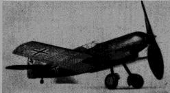
A hard-balsa block 7/8" x 1-1/2" x 7-1/2" is required for the propeller. Shape the blank as shown and then carve a righthand prop. Cut the back face of the blades first; a bit of under camber is desirable. Reduce the front of the blades to the desired thickness. Shape of the blades can be determined from the photos. Apply several coats of clear dope with light sanding between each to produce a smooth finish. Make the spinner in two pieces and cement to the sides of the hub. It is advisable to use some simple free-wheeling device to help improve the glide. A washer is glued to the back of the propeller to make it revolve freely.
The removable nose plug is shown on the plan. A disc of 1/32' plywood is used for the front portion and a piece of very hard balsa for the back. Drill a small hole through the center and cement washers to both sides to fix the line of thrust. .040 in. music wire is used for the propeller shaft. Slip the nose plug, several washers and the propeller on the shaft in the order given. If a winder or free-wheel device is to be used, bend a loop in the end of the shaft; otherwise bend the end at a right angle and force into the hub.
Eight to ten strands (four or five loops) of 1/8" flat, brown rubber are used to power our model Messerschmitt. Lubricate the rubber strands and then wipe off the excess to prevent splashing the sides of the body. Hook one end of the loop to the prop shaft and drop the other end through the body. It may be necessary to remove a small portion of the covering in the rear to aid in fitting the bamboo pin into position to hold the rubber strands.
Flying
It is, indeed, very seldom that a model will fly perfectly from the start, so it is evident that the success of any model is usually determined by the builder's ability to analyze and correct improper flight attitudes Now, that statement does not infer that this model is especially hard to adjust and fly; for on the contrary our Me-109 was made to fly excellently with but a few minor adjustments.
The following suggestions can be made to aid in making your ship fly properly: To begin with, your testing grounds should be free from trees and other "model catchers" that might damage the plane before it has had an opportunity to demonstrate its ability. A field with tall grass or deep weeds is best. Try a few shoulder height glides to detect any error in balance. In all probability a small weight in the nose will be required to obtain the desired results. Wind the rubber motor about 50 turns and try a power flight, Right- or left-thrust will make the model circle as desired and a slight amount of down-thrust will correct a tendency to mush or stall while under power. Gradually increase the number of turns as the flights become more satisfactory. Stretch the rubber strands about 2-1/2 times normal length and use a mechanical winder for real flights. Our test model was adjusted to fly in a large left circle while under power and it glides to the right. It is capable of making flights of nearly a minute.
Scanned from
FLYING SCALE MODELS
![]()
![]()
![]()
![]()
[ Home ] [ Previous Plan Pages ] [ Special
Things ] [ Earl Stahl Plans ]