The Plan Page
[ Home ] [ Previous Plan Pages ]
[ Special Things ] [ Earl Stahl Plans ]
gt-hunter1@home.com
BUILD AND FLY THIS RUSSIAN FIGHTER
Complete data and plans to construct a flying
model of the famous high speed Soviet fighterMIG‑3
by EARL STAHL
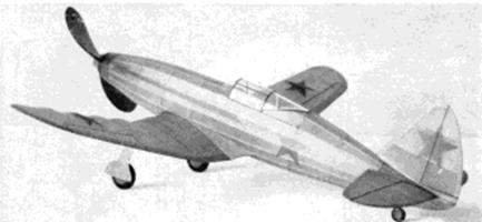
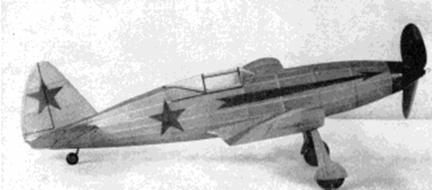
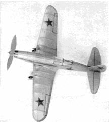
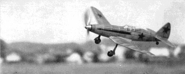
Top Here she comes around the first turn at full speed (a real flight picture). Above and below Two
views showing its smooth efficient lines and realistic effect when carefully decorated
NEARLY two years of war has proved the Soviets have aircraft of modern design and outstanding performance. Probably the fastest and most formidable fighter of the Red Airforce is the 1-18 or MIG-3 single seater. In appearance it bears a marked resemblance to the early Curtis XP-37 from which the now famous Curtiss P-40 was developed.
Specific information about all warplanes is a closely guarded military secret, however a few details about this fighter are known. The sleek-lined 1-18 is powered by a 12 cylinder, liquid cooled Mikouline engine of 1,250 hp. which is said to give a top speed of more than 360 mph at 13,000 ft. Wing span is 36 ft. 6 in.; length 32 ft. and gross weight, 6,200 pounds. Armament consists of four machine guns and two cannon. Construction is unusual in that the forward part of wing and fuselage are metal while remainder of the structure is plywood.
So much for details of the real fighter. The sleek, graceful lines of the 1-18 make it an attractive subject for a flying scale model. Because of its excellent proportions it is ideally suited for flying and the author must add that his 1-18 is without exception one of the best low‑wing scale models he has built.
The model is constructed in the conventional manner. While the test ship was designed for and incorporated balsa wood in the structure, it is readily adaptable to construction using slightly heavier white pine and basswood flow being sold in some model shops. All wood should be selected carefully to assure the strongest structure possible. In the process assembly all frames.
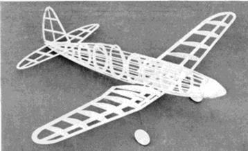
Above The completed framework, light and sturdy
Below Ailerons, elevators and cabin are lined in black
should be made with accuracy and each joint cemented firmly.
CONSTRUCTION: The manner of fuselage construction calls for use of four keels cut to shape from 1/16" sheet. To obtain their patterns, trace the top, bottom and side outlines of the body. Bulkheads, likewise 1/16" sheet, are cut in accordance with patterns given. Cut only the notches shown leaving the others to be cut as a later operation; their positions should be marked, however, for reference.
Pin the top and bottom keels to position over the side view and then cement half the bulkheads to place. Attach a side keel and then, when dry, remove structure from the plan and add remaining bulkheads and keel. Stringers are 1/16" sq. stock. Attach the ones nearest the side keels first, cutting notches as required. Always attach stringers to corresponding positions of each side at the same time to prevent pulling the body out of line.
Between bulkheads C and E, where the wing fits in, curved pieces are cut from 1/16" sheet and fitted so as to make the fuselage sides fit to the wing curvature. Other items to be assembled to the fuselage are the curved pieces of 1/16" sheet which form the back of the cockpit enclosure and the small blocks of hard sheet stock in the rear which anchor the rubber motor.
The nose block, just forward of bulkhead A, is made from two pieces of 1/4" sheet balsa cemented cross‑grain. Cut out the center for the nose plug, then roughly cut to shape before cementing to the nose for final finishing, by using rough and then fine sandpaper.
For those builders using white pine or bass it is suggested the same procedure of construction be followed but bulkheads of 1/32" or 1/20" thickness should be sufficiently strong. Stringers of 1/32" x 1/16" size placed with the narrowest side next to the covering will be of about the same strength and weight; if this size stringer is not available, 1/16" sq. stock sanded smaller will be all right.
Few details are required to outline the method of constructing the tail surfaces. Study the plans and it will be noted that both stabilizer and rudder are made in a like manner from 1/16" thick stock of the indicated width. Make flat frames of both (the stabilizer is made in one piece) then when the cement has set, remove from the jigs and cement soft 1/16" sq. strips to each side of each rib. These are later cut to the streamline shape indicated and edges are tapered to conform to the rib shape.
If it is necessary to use wood other than balsa for the stabilizer and rudder, it must be remembered that they must be of light but strong construction. To accomplish this, reduce the size of the various parts and eliminate streamline cap strips over the ribs. Cement everything well so there will be little tendency to warp.
The wing is easiest assembled in one piece: the builder will have to make a left side plan, as there was insufficient room for it on the drawings. Ribs are cut from 1/32" sheet except as noted and two of each is needed except No. 1. Sand them carefully to exact size and cut the notches for spars. Spars and leading edge are cut from sheet stock as indicated and the trailing edge is a tapered strip of 1/8" x 3/8" stock. Tip pieces are cut from 1/8" thick material and are assembled over the plan. With pins hold the various parts in place over the plan until the cement has set. When dry, crack the spar and edges and elevate the tips to indicated dihedral: recement the joints firmly. Finally trim and sand the leading and trailing edges to conform with the airfoil shape.
To keep weight at a minimum the builder using heavier wood will have to use material of smaller crossection, particularly the leading and trailing edges. Ribs should be cut from the thinnest stock and lightening holes at points of little stress will reduce the overall weight.
A landing gear of the type used on the model 1-18 is very rugged yet accurate in appearance; it is easily made from .040 music wire. The top of each strut is bent in such a manner as to join the spars and rib No. 4. Be sure to make a right and left strut. With thread bind the struts to the spar and then use a needle and thread and sew right through the rib and about the wire. Strengthen the whole area by applying several coats of cement. The rubber tubing (or any other kind of tubing) and balsa lauding gear covers are not added until later.
Lightweight wheels can be purchased or they may easily be made from scraps of 1/8" sheet balsa that have been laminated together. Washers or bearing should be attached to each wheel so they will turn freely and accurately.
Select a very hard balsa or soft white pine block of the correct size for the propeller. Drill the tiny hole for the prop shaft and then cut out the blank as shown. A right-hand prop is to be carved. Cut away the back face of the blank first until the backs are as desired, then cut away the front until the blades are of the proper thickness. Reduce the depth of the hub and shape the blades in a manner similar to the prop on the original model. With rough and then fine paper sand the propeller to a smooth finish. Shape the spinner from a light grade balsa block, then notch it to fit over the prop hub. Before the spinner is attached permanently, the type of freewheel gadget to be used, if any, should be considered and provisions made for it. Apply several coats of clear dope with light sanding between each to smooth and harden the surface.
The removable nose plug is shown in perspective. A disc of 1/32" plywood forms the front portion while the back is laminations of 1/4" sheet balsa. Fix the line of thrust by cementing washers to the front and hack of the plug.
For the propeller shaft use .040 music wire. A loop to which a mechanical winder can be hooked should be bent on the front of the shaft. Place several washers between the propeller and nose plug to reduce friction.
Work over the entire structure with fine sandpaper to prepare for a neat cover job. Regular colored tissue or silkspan is used and banana oil or thin dope is the adhesive. Use individual sections of tissue for each flat section of each side of the wing, tips, tail surfaces, etc.
In covering the fuselage it will be necessary to use numerous small pieces to work around the curves without wrinkles: the tissue must be lapped carefully to assure a neat job. Lightly spray the covered parts with water to tighten the tissue. The flying surfaces must be supported level while drying so they will not warp.
Assemble the covered parts in this manner: Fit the wing into the recess in the fuselage and cement it fast - if the structures have been made with accuracy, the incidence will be correct. Wing fillet patterns are given and two are cut from 1/32" sheet. They are to fit accurately from fuselage to wing and may need a bit of alteration to fit exactly on your model. If the builder desires, the trailing edge of each fillet may be strengthened by laminating another small piece of 1/32" sheet to the underside. Finish the opening from wing to fuselage on the bottom with 1/16" sq. strips and then cover this area and the fillets with colored tissue. It will be necessary to temporarily cut the top keel and last bulkhead to admit the stabilizer, which is cemented fast at the angle shown. Cement the rudder to place with a bit of offset to counteract torque. Tissue fillets are placed between the tail surfaces and fuselage. Any wrinkles in the covering should be moistened with water and permitted to dry before the entire model is given a coat or two of clear dope.
Now to add the more minor details. The cockpit enclosure is made from thin celluloid. Make paper patterns of each section of windshield before cutting the parts from celluloid. When cementing to place be careful to avoid cement smears. The structural detail is represented by doping thin strips of black tissue to the transparent enclosure. Rubber (or similar) tubing of the correct diameter is slipped over the vertical portion of the landing gear wires. Wheels are colored and then held to the axles by small washers soldered to the ends. The outer landing gear covers are cut from 1/32" sheet and then covered with tissue to match the rest of the plane. The red Russian star and other decorations can be cut from colored tissue and doped to the covering. Control surface outlines are simply thin strips of black tissue doped to place, Items such as the tail wheel, exhaust, ports, etc., are made from scraps.
FLYING: Our original test model is powered with six strands (three loops) of 3/16" flat, brown rubber. It is best to lubricate the motor before placing it within the fuselage. Hook the strands to the prop shaft and then drop the other ends through the fuselage. It may be necessary to remove a small portion of the covering in the rear in order to get the strands into position to be held by the removable bamboo pin.
Make first flights over soft grass but if none is available, make first tests R.O.G. with but a few turns. In all probability the model will be out of balance so a small corrective weight may be needed. As correct balance and stability are attained increase the number of turns. Off-setting the thrust line will aid in controlling the amount of circle in either direction, and by tilting the thrust line down a tendency to stall can be eliminated. For maximum performance stretch the rubber motor and wind with a mechanical winder.
V I C T 0 R Y
Scanned from January,
1943
Model Airplane News
![]()
![]()
![]()
![]()
[ Home ] [ Previous Plan Pages ] [ Special
Things ] [ Earl Stahl Plans ]