The Plan Page
[ Home ] [ Previous Plan Pages ]
[ Special Things ] [ Earl Stahl Plans ]
gt-hunter1@home.com
FLYING SCALE
NAVION
by EARL STAHL
Member, A.M.A
NORTH AMERICAN'S
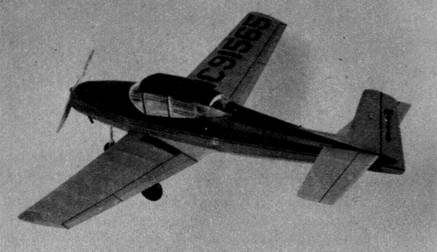
NAVION IN FLYING SCALE
MODEL FORM HAS WHAT IT TAKES
In the belief that the currently popular small, light aircraft are not the answer to the much talked about "family plane" problem, a number of manufacturers are bending their efforts towards the production of larger, speedier craft that are not too tricky for the non‑professional pilot to fly. Such a plane is the Mustang like Navion now rolling off the assembly lines of North American Aviation's factory.
With seats for four and a range of more than six hundred miles, it more nearly approaches the utility of an automobile. Further to bring it more nearly on a par with a car, appearance and comfort of the cabin have been carefully considered. The similarity ends, though, when speed enters the picture, for the Navion's effortless cruising straight to its destination at 150 miles per hour outdistances the tortoise‑like car slowed by hills, curves, and traffic beyond fair comparison.
Those who have flown the ship say it handles well and is safe in the hands of the average sportsman pilot. Sturdy all metal construction, based on experience gleaned from fabrication of the AT-6 Texan and the P-51 Mustang is featured. A tricycle, retracting landing gear is employed for better take-offs and landings and to improve the taxiing characteristics on airports. All in all, the Navion marks a forward step in safety for planes of this class.
With all these desirable characteristics it would seem that every family should have on order a Navion or a competitive Beech Bonanza, Stinson Voyager, or Republic Seabee. Yet the fact remains that the prices of these craft, ranging from more than five thousand dollars for the Voyager to nearly eight thousand for the Bonanza, are equal to that of a modest home and is simply beyond the reach of all but a comparative few. So until such time as efficiency of production dips the costs to the level of a good car, most of the planes will go to airport operators, companies that can employ them in the conduct of their business, and a few of moderate means. The rest of us will continue to wedge ourselves into the small, noisy, drafty cabins of our "putt-putts" to bob along the airways at a hundred miles per or less - if, indeed, we are flying at all.
From the standpoint of a model, however, the financial angle is not so discouraging, since for a dollar or so and a few hours of labor (or fun?), a snappy appearing, high flying replica can be had. We have been building flying scale models of all kinds for nearly a decade and can say that the Navion is one of the best we have ever had. Designed from drawings supplied by North American, the model captures the eye appeal of the prototype, yet it is a real flyer showing remarkable power and stability as it climbs in wide circles and then floats back to earth in a smooth glide. Generally, the craft is scale (proportions, dihedral, etc.); however, our experience has shown that adjustment of incidence of the flying surfaces is required to get really good results; we have made these minor changes in the interests of top performance
The construction sequence is outlined briefly and no difficulty should be experienced if drawings are studied and text is read before starting. Balsa wood is used throughout and colorless model plane cement is the adhesive. Work carefully to reap the reward of keener appearance and finer flights.
Construction is logically begun with the fuselage. The structure featured is light and strong, yet easily made. It consists of four keels (top, bottom, and two side) cut to the outline shapes shown; to these bulkheads and stringers are attached. To accomplish the job, first cut all parts from medium grade sheet stock. Then pin the top and bottom keels to place over the side view and cement half of the bulkheads and one of the keels to place. Now lift the structure from the jig and place the remaining parts. Stringers are hard 1/16" sq. strips added to respective positions on each side at the same time to preserve the alignment.
Numerous details must be completed before the job is done. Between bulkheads C and E, where the wing fits in, attach curved pieces to make the wing's top surface fit to the fuselage as shown. The nose block is laminated sections cut to the shape of bulkhead A and then later finished as shown. To simulate the metal cowl, and for added strength, too, the shaded areas of the nose are filled in with rectangles of soft grade 1/8" sheet balsa, which are then cut and sanded smooth. The small section of cabin roof forward of D is carved from soft balsa and pieces of balsa are fitted to the rear of the cabin to attain the shape shown. Aft of bulkhead J sections of very hard 1/8" balsa are inserted to retain the removable bamboo pin.
Since only the left wing is shown on the drawings, a rightwing plan must be made so parts can be assembled over it. Once all parts are cut, ribs as shown, leading edges from1/8" sheet, spars from 1/16" sheet, and tips from 1/8" sheet, assemble the parts to form two halves. Then join the halves with 2-1/4" dihedral at the tips. Finally, trim the leading and trailing edges to the cross-sectional shape indicated.
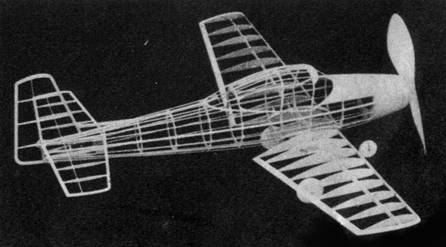
Designed directly from plans supplied by
North American, the framework
of this scale model can be relied upon for accuracy and sound construction
Tail surfaces are light and strong and both are built similarly. Cut the outlines from 1/16" sheet and pin them over full-size drawings. Add spars of 1/16" sq. strips and then ribs of the same stock. Lift these frames from the jigs and add the over rib sections as shown by the sketch. To complete the structures, cut and sand the leading and trailing edges to conform to the streamline cross section.
The landing gear is usually a problem to builders of flying scale models, but if one of the type shown is incorporated on your model, it will prove to be nearly indestructible, yet most realistic. Bend the struts for the rear gear from .040 music wire. Some dimensions are given and the ones missing are simply made to fit to parts already made. With thread, bind and sew these to the spars and ribs as shown. The nose gear is made in two parts from .030 music wire and the two halves are then soldered together. Sew this nose strut directly to bulkhead B and glue firmly. Pieces of rubber tubing of various diameters are slipped over struts for realism; it will be necessary to split the tubing for the nose gear to get it in place.
For good flights a flying type propeller must be carved. Dimensions and shape of the block are given and white pine is the suggested wood for use. Carve a right-hand prop, rounding the blade shape nicely. The shaft for the propeller is .040 music wire and it is bent to the shape shown. The front end may be bent to fit to a free-wheel gadget that will permit the blades to spin freely in the glide and thus lengthen the time of descent.
The removable nose plug to which the prop is attached by the shaft is made from a disk of 1/32" plywood (birch) which has a cross-grained cube of balsa at the back. This plug fits into the nose block and is removable facilitate installation of the rubber motor; it also allows it to be stretched before winding. Incidentally, be sure to put several washers between prop and nose plug to minimize friction.
A scale prop is shown, too, and on our model we used one featuring light and dark laminations for added realism. The prop shown on the drawing is the fixed pitch type used on the first Navion's; later ships have adjustable wood ones of slightly different shape.
Before frames are covered - they should be sanded to allow a neat job to be made. Install the thin celluloid windows before covering, but do not assemble the various parts at this time. We used colored tissue on our test job because it is both light and attractive. Cover parts carefully, using as many small sections of tissue as are needed to avoid wrinkles. Banana oil or thinned dear dope is the adhesive used to stick the paper to the frames. When the covering job is done, lightly spray with water to tighten it, but do not apply any dope until later when the model is assembled.
This assembly job is next and is done in this manner; fit the wing into the slot and cement it fast. Approximate shape of the fillets is given and they may require slight altering for individual ships to span the gap from wing to fuselage neatly. Cover the fillets with colored tissue as well as the openings at the fuselage bottom. Slip the stabilizer into the slot provided for it and cement it fast. Offset the rudder about 1/16" for a right turn and be sure it is properly aligned when installing. The whole model may now be given two light coats of dope.
Trimming and details complete the construction task. Colored tissue was used for stripes and numerals on the model shown but decals may be substituted. The balsa wheels, exhaust stacks, etc., should all be painted before being attached. Check pictures of the real ship for added minor details that may be added to the extent of the builders' ability and initiative.
Now that the ship is about ready for flights, a rubber motor is needed. Get 3/16" flat brown rubber if possible and make an eight-strand motor of it. Incidentally, it should be lightly lubricated with a mixture of tincture of green soap and glycerin. Hook one end of the motor to the prop shaft and drop the other ends through the opening in the nose. The removable bamboo pin is slipped across the back of the fuselage to hold them.
Just as important as the careful construction of the model is its adjustment to fly properly. Every experienced builder knows that it is rare indeed that a ship will fly perfectly upon completion but rather it requires minor readjustments of the location of the center of gravity, slight relocation of the thrust line, or even a little warping of the flying surfaces to squeeze all of the potential performance from it. With this in mind strive to make your "Navion" a real flyer rather than just another model.
Of course, no model will last long if it is confronted by trees and houses at every turn of the prop, so get out in a nice grassy field on a calm day to test hop your Navion. Hand glides come first to check the balance. If it stalls add weight within the nose, and should it dive (which is unlikely) a small weight is needed at the tail. With the glide reasonably good, try short power flights observing both power-on and gliding attitudes. Make any gliding readjustments with weight (or if it turns too sharply in the glide, warp the rudder a bit) and then correct any unstable power tendencies by off-setting the thrust line. This is done by placing a sliver of wood between the nose plug and nose at the top to get down thrust which will iron out a tendency to stall while under power. Right thrust achieved in the same way will control the size of circles. As flights improve, increase the number of winds until a mechanical winder is employed and the rubber is stretched out through the nose about 2-1/2 times normal length before maximum power is stored up.
Our original Navion flew best when it was adjusted to climb steeply in a shallow left bank and then as power diminished it slowly veered right to glide down in sweeping right spirals. Treat your Navion right and it will treat you to countless hours of enjoyment in flying.
Scanned
From August, 1947
Air Trails and Science Frontiers
![]()
![]()
[ Home ] [ Previous Plan Pages ] [ Special
Things ] [ Earl Stahl Plans ]