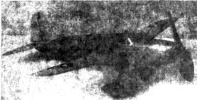
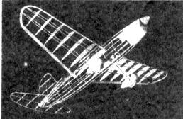
It has sleek realistic lines, just like its large counterpart.

A wide blade prop gives plenty of climb.
The Plan Page
[ Home ] [ Previous Plan Pages ]
[ Special Things ] [ Earl Stahl Plans ]
gt-hunter1@home.com
|
It has sleek realistic lines, just like its large counterpart. |
A wide blade prop gives plenty of climb. |
Building A Flying
NAVY SCOUT
A Realistic Fine Performance Model
of Uncle Sam's New Navy Gun Spotter
By EARL STAHL
 Cockpits for pilot and observer are enclosed. |
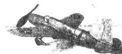 Large tail surface gives steady flight. |
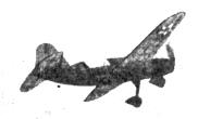
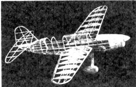 The frame is sturdy, light yet flexible, to withstand shocks. |
 The reinforced nose helps to prevent damage. |
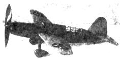
 In full flight - most realistic. |
Newest scout-observation plane being produced for the U.S. Navy is the trim little Curtiss SO3C-1. As such, it is designed to perform the various duties required of planes operating from cruisers and battleships. It can be used either as a landplane or seaplane, its chief function, however being that of catapult launched seaplane.
Frequently referred to as the "eyes of the fleet" it is the military mission of these ships to direct the fire of the battleships’ big guns and conduct long range scouting activities in search of enemy surface vessels and submarines. In addition to these tasks the "S-O" planes lay protective smoke screens around friendly naval craft and fighting activities.
In design the SO3C-1 is a two-seater, mid-wing monoplane. An inverted, air-cooled Ranger 12 cylinder engine of 520 horsepower is installed. With the exception of the fabric covered tail surfaces, construction is all metal. As a landplane, the ship is equipped with a fully faired, non retractable landing gear; when being used as a catapult launched seaplane, a large single main float and two small wing tip floats are installed.
Compared with modern share or aircraft carrier based aircraft, the performance is not starting; nevertheless it is considerably improved over that of the old Vought "Corsairs" and Curtiss "Seagulls" (SOC-1) formerly assigned to this task. Top speed is in the neighborhood of 200 m.p.h. while cruising speed is 146 m.p.h. Specially designed slots and flaps keep the landing speed at less then 60 m.p.h. The fuel load of 199 gallons should give a cruising range of more than 1.000 miles.
The Curtiss SO3C-1 is not heavily armed. An electrically controlled machine gun is located in each wing half just outboard of the propeller arc. The observer is provided with a single gun which is exposed when the panels to the rear of his cockpit are lowered. Racks for small bombs may be installed under the wings and when flown as a landplane, a small torpedo may be carried beneath the belly.
Because of its ideal proportions and relatively simple structure, the SO3C-1 is readily adaptable for a flying scale model. Our little ship is a faithful reproduction of the prototype and for that reason makes an interesting model to build and fly. If carefully built from the accompanying plans, this little naval scout will take to the air as readily as "a duck takes to water".
Construction of the model is not difficult; before work is started, the pages of the plans should be properly joined. Select all balsa wood carefully so the structure will be as strong and light as possible. Cement all joints firmly checking frequently for correct alignment.
Fuselage
The keel and bulkhead method of construction is employed for the fuselage. Exact size bulkheads are shown on the plan; two of each are required (except No. 5 of which four are needed). They are cut from medium grade 1/16" sheet. Cut only those notches indicated; others will be cut later as required. Four keels are necessary; the top, bottom and the two side ones. The side keels are clearly shown and the shape of others is obtained by tracing the top and bottom outlines of the side view - average depth is about 5/64" and they too are cut from medium 1/16" sheet.
To begin assembly pin the top and bottom keels to position over the side view. Next cement half the bulkheads to place in a vertical position. Add the side keel and check for correct alignment. When dry, remove from the plan and add the remaining bulkheads and side keel to their respective positions. Check and recheck the structure to be certain that it is true.
Stringers are rather hard grade 1/16" square stock. Attach those nearest the side keels first; add a stringer to each side at the same time to avoid pulling the structure out of line. Where there are no notches for the stringers, they are easily cut using a razor blade that has been broken to a sharp sliver.
"Filling - in" the nose adds to the strength and attractiveness. The area shown lightly shaded on the plan is to be fitted with individual pieces of soft 1/16" or 3/32" balsa neatly cut to fit snugly between the stringers and bulkheads. Cement two pieces of 1/4" sheet together for the nose block; cut to outline shape and remove the square section into which the nose plug fits. Roughly cut to shape and then cement the nose block to bulkhead No. 1. Cut and sand the entire nose to a smooth, accurate shape.
As shown, 1/16" sheet gussets are cemented to the fuselage to reinforce the wing mount. Cut two rib shaped wing mounts from hard 1/16" sheet and cement them to place with their base exactly parallel to the stringer; cement very firmly. The 3/32" thick blocks in the rear which hold the bamboo pin can be added also.
Landing Gear
To prevent damage to the model the landing gear must be able to absorb all shock encountered in normal flying. First make a complete pattern of the wire strut, then bend to shape from .040 music wire. A 1/16" sheet former is made, as indicated in the landing gear detail; it should fit snugly within the wire strut top. Cement the former to bulkhead No.4 and then slip the wire over it and attach by sewing with needle and thread. Make the fairing struts from 3/16" sheet. They are of streamline cross section and have a shallow groove in the back to hide the wire strut.
Wheel pants and wheels are made from laminated sheet. Remove the centers of the inside pieces to admit the wheels. Cement the parts together and then cut to shape; looking from the top the shape is streamline. Sand the pants thoroughly and apply several coats of dope for a nice finish. Each wheel is made from two discs of 1/8" balsa cemented cross-grain. The fairing struts, wheels and wheel pants are not attached to the wire struts until later.
Tail Surfaces
Tail surfaces constructed in the following manner are both light and strong; both rudder and stabilizer are made similarly. Working directly over the plans, make complete frames using hard 1/16" sheet for the outlines, 1/16" x 1/8" strips for the spars, and 1/16" square for the ribs. When dry, lift these flat frames from the plan and add soft 1/16" pieces to each side of each rib. To complete the construction cut the ribs to a streamline shape and finish the leading and trailing edges to the indicated shape
.Wing
The wing is of multiple spar construction. Since only one half the wing plan is shown, it will be necessary to make a full scale drawing of the left wing. All ribs except No.1 are cut from 1/32" sheet; two of each are required. Sand the ribs smooth and then accurately cut the notches. The leading edge shape is shown in broken lines over the wing plan - cut two from 1/8" hard sheet. Taper the trailing edges before pinning to place over the plan. Wing tips are cut from 3/32" stock; the pieces should be assembled directly over the plan. Pin the various parts to their respective positions; then cement all joints firmly. The spars are hard grade 1/16" square strips. When the cement has hardened, lift the wing halves from the plan and cut and sand the leading edges and tips to their finished shape.
Propeller
The propeller blank is shown in perspective on the plan. Select a hard balsa block 8" x 1-5/8" x 1"; accurately cut the blank to indicated shape. Drill the tiny hole for the shaft and then start to carve a right hand propeller. Finish the back surface of the blades first; a bit of undercamber should be sanded in each blade. Cut away the front face until the blades are of the desired thickness. Shape the blade outline similar to that in the photos. Sand with rough and then fine sandpaper until the blades are perfectly smooth and in balance. Carve the spinner in two parts from soft balsa and then cement to the hub sides.
Nose plug details are given. The front disc is cut from 1/32" birch plywood while the rear portion is laminated squares of 1/8" sheet. The plug fits neatly to the nose block. Cement washers to the front and rear of the plug to fix the line of thrust.
Bend the prop shaft from .040 music wire. Slip the nose plug, several washers and the propeller on the shaft in the order given. Bend the shaft front end to suit the free-wheel gadget being used. A loop in the end into which a winder hook can be attached is recommended.
Covering
Prepare the frames for covering by working over the entire structure with fine sandpaper. The author likes to sand the bulkheads to a scalloped shape so only the stringers will touch the covering; this aids in making a better job. Regular colored tissue is used and thin dope or banana oil is used for adhesive. Use a separate piece of tissue for each side of the wing halves, rudder and stabilizer; tips, etc., require individual pieces. When covering the fuselage it will be necessary to use numerous small pieces to work around the curves without wrinkles; lap the pieces of tissue neatly. Cover the balsa nose, etc., too. Spray the covered parts lightly with water to tighten the tissue but do not apply dope until the ship has been assembled.
Assembly
Your model is now ready to be assembled, let’s complete the landing gear first. Flow cement into the groove in the fairing struts and then fit them over the landing gear wires - do not attach the struts to the fuselage structure, however. A strip of silk cloth over the strut and wire will keep it from becoming loose. Next cover the struts with tissue to match the fuselage. Cement washers to the sides of the wheels before coloring the centers and tires. Place the wheels within the pants and slip both on the axle; attach firmly with cement.
Windshields come next. Obtain very light celluloid, especially for the rear cockpit. No frame other than that shown on the plan is needed; simply form the celluloid by rolling between the finger, then neatly attach with cement. Front windshield pattern is given. Structure of the real plane’s windows is represented by tissue strips doped to place.
Since the plans were drawn, it was found that for best flight performance the stabilizer front should be lowered 1/32" to give it a negative angle. Cement both stabilizer and rudder to place; offset the rudder a bit for a right turn in the glide. Check the tail surfaces for correct alignment. Small tissue fillets neatly doped to place will improved the model’s appearance.
Scrape all tissue away from the wing mounts before cementing the wings fast; use plenty of cement. Make the incidence of each wing exactly as shown. Wing tips are elevated so the dihedral at each tip will be 1-3/8".
Addition of the various minor details completes the construction. One or two coats of thin dope should now be brushed an the whole model; if a bit colored dope is added to the clear liquid, it will make a better job. Of course the propeller, wheel pants, etc., must be colored doped; use several coats with light sanding between each for the best job. The stars, U.S. Navy and other details are made from colored tissue. Ailerons, flaps, elevators and such details are represented by thin strips of black tissue neatly doped to the covering. Add a tail wheel, cowl details, antenna and similar items to suit your ability and ambition and your SO3C-1 is completed.
Flying
Depending on the model’s weight, eight strands of 1/8" rubber or six strands of 3/16" rubber will be required for power. Lubricate the strands, hook them to the prop shaft and then drop the other end through the fuselage. As shown, a bamboo pin holds the motor in the rear. If necessary, remove a small portion of the covering to aid in getting the motor in place. Incidentally, small slits should be cut in the fuselage covering at the point of landing gear attachment so the struts can spring backward without damaging the covering.
In all probability your Curtiss will need a small corrective weight in the nose or tail to bring the model into balance; our own ship needed a tiny piece of lead in the nose. Make first flights over a grassy field to prevent damage while necessary adjustments are being made. First adjustments should favor the glide, then offset the thrust line to correct the power flight. A sliver of wood at the top of the nose plug, tilting the thrust line down, will in all probability "iron out" a stall, while right or left thrust, as needed, will control the amount of circle. Gradually increase the number of turns as flights improve. Stretch the rubber motor two to three times normal length for best flights.
Our test plane proved to be a realistic performer. However, like most models of combat planes, it is sensitive to all adjustments which therefore must be made with care. The model pictured climbs in a large left circle at a steep angle and fast rate of speed - it really seems to inherit some of the real plane’s "zip". In the glide it descends in easy right circles. After many flights our Curtiss SO3C-1 remained undamaged except for a few patches in the covering. Many happy landings with your little naval scout!
Scanned form December 1941
Model Airplane News
![]()
![]()
![]()
![]()
[ Home ] [ Previous Plan Pages ] [ Special
Things ] [ Earl Stahl Plans ]