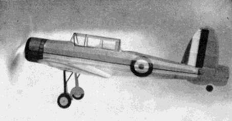
Model in actual flight, not posed
The Plan Page
[ Home ] [ Previous Plan Pages ]
[ Special Things ] [ Earl Stahl Plans ]
gt-hunter1@home.com
RIGHT OFF THE FLIGHT DECK
Build and fly this
thrilling miniature of Britain's
most famous "carrier" fighter the Blackburn Skua
Model in actual flight, not posed
by EARL STAHL
THE Blackburn Skua, two-seater fighter and dive‑bomber, one of the most widely used weapons of Britain's powerful Fleet Air Arm, is designed to meet the exacting demands of aircraft carrier planes. Because of its deadly striking power, wide range and fine performance, it is considered a most formidable fighter.
Structurally a low-wing monoplane of all metal construction, the Skua is similar in many respects (except beauty of line) to the Vought Vindicator scout-bomber of our own navy. Like the Vindicator, wings fold to conserve deck space yet they are strong enough to take the stress of screaming dive-bombing attacks and sharp pull-outs once the explosives are released. Flaps at the wing trailing edge reduce diving speed and for slow approach upon boarding. An arresting hook lowered from the fuselage belly stops the craft on deck. The plane is divided into a number of water-tight compartments to keep it afloat in the event of emergency landing. A very complete set of navigation equipment makes possible long over-water flights.
Offensively and defensively the Skua is a powerful foe. In special racks beneath the wings nearly a half ton of bombs of varying sizes and types can be carried. Four forward firing machine guns jut from the wing leading edge and the observer's cockpit is equipped with two free-firing Brownings. The engine is Britain's famous air‑cooled, sleeve valve 900 h.p. Perseus producing maximum speed of 250 m.p.h.
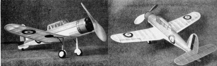
Built in careful detail, it is most realistic and
thrilling in flight.
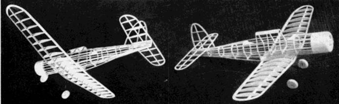
The light yet strong and efficient structure is clearly evident
A modified version of the Skua is the Blackburn Roc. In most respects this plane is similar except that it is fitted with one of those deadly, power driven, multi-gun turrets. The enemy is blasted from the sky by flying along side and delivering a terrific broadside.
Despite its rather unusual appearance, the model Skua is interesting to build and fly. We have accurately reproduced the prototype appearance and flying qualities, yet the construction is comparatively simple. The original model was capable of making graceful, high altitude flights of about 60 seconds duration.
The pages of plans are drawn full size and the two pages with fuselage details should be joined together. It is best to make tracings of the various pages to keep the magazine intact. All balsa wood should be selected carefully to assure a sturdy, light structure; make all frames accurately and finally cement each joint firmly.
CONSTRUCTION- Construction can be started with the wing which is made in three parts and it will be necessary to make a left wing plan. Cut the required number of ribs from 1/16" or 1/20" light grade sheet balsa - preferably the later, if available. Sand them carefully to exact shape and size and cut the notches for the spars. Spars and leading edges are cut from sheet stock as indicated and the trailing edge is a tapered 1/8" x 3/8" strip. Tips are cut from 3/32" sheet and assembled over the plan. Assemble the parts right over the plans using pins to hold in place until the cement has set. Finish the parts by cutting and sanding the tips and edges to conform with the airfoil shape. The three parts are next assembled with 2" dihedral at each tip.
The keel and bulkhead method of construction is employed for the fuselage. Notice how the bottom of the fuselage has a curved recess into which the wing is later fitted. Cut the various parts for the four keels - top, bottom and two sides, from 1/16" sheet as shown. Bulkheads also are 1/16" sheet and only the notches shown are cut out; others are marked to be cut later. Assemble over the plans by pinning the top and bottom keels to place. Half of the bulkheads are cemented to position and a side keel attached. Now remove from the plan and add the remaining bulkheads and keel. Stringers are firm 1/16" sq. stock. Attach stringers closest to the side keels first and on both sides at the same time to keep from distorting the fuselage. Cut notches as required for a neat, accurate job. Where the wing fits in, curved 1/16" thick pieces are cut to fit exactly to the wing's upper surface.
From section A to B the nose can be covered with 1/32" sheet or pieces of soft 1/16" sheet can be fitted between the stringers and bulkheads and trimmed round to represent the metal cowl of the real ship. Either method is satisfactory; we used sheet covering on our model. The extreme front of the cowl is made with laminated discs of 1/8" sheet. Remove the centers of the two front discs so a dummy motor can be installed if desired. Trim to shape with a razor blade, then sand to complete the cowl. Details of the nose plug are given and it too is made from laminated discs of 1/8" sheet (hard grade). Cement the back portion within the cowl; the front is removable to permit stretching the rubber motor for winding. As shown, a hole is drilled for the prop shaft and washers are cemented to the front and back to fix the thrust line.
Patterns for the cockpit are given that fitted the test model but they may need slight altering for your plane. Select 1/32" sheet that bends well and cut them full size, then cement to place. Soft sheet was used for the cockpit roof from D to F but colored tissue doped to the celluloid cover, when later attached. looks just as realistic. Cut the sub rudder from soft 3/32" sheet and sand to a streamline shape before cementing fast. Small blocks of hard 3/32" sheet are glued between the stringers in the rear to hold the removable bamboo pin.
Little explanation is needed for the tail surfaces. Study the plans, note that both stabilizer and rudder are built of 1/16" thick stock of the width indicated. Make the whole stabilizer in one piece, then when the cement has set, remove both stabilizer and rudder from the jigs and cement soft 1/16" sq. strips to each side of each rib. These are later streamlined as indicated and the edges and tips tapered to conform with the rib shape. Parts so constructed are light yet strong.
Landing gear struts are attached to the wing and details are clearly shown. While hardly necessary, simple full size sketches of each part can be made. Bend the parts to size from .040 music wire being careful to make a right and left unit. The two elements of each strut are soldered together. Bind the one strut to the special landing gear spar then with needle and thread sew the rear one right to the rib. Coat the thread and adjacent areas with several applications of cement. The rubber tubing covers, etc., are not added until later.
Wheels of the correct size are purchased or they call be made from laminated discs of 1/8" sheet. Regardless of the type, they should be fitted with bearings or washers for free and accurate spin. Wheels are not permanently attached until later.
For any model to fly well requires an efficient propeller. An 8" diameter propeller is recommended for the model Skua. Select a hard balsa block of the required size and cut out the blank as shown. Drill the hole for the prop shaft then carve a right hand air screw. Work carefully and do a good job. Round the blade tips and reduce hub thickness -- examine photographs of the original model for further details. Use rough, then fine sandpaper to finish and balance the blades. Several coats of light dope with sanding between each hardens and smoothes the surface. A free-wheel gadget attached to the propeller improves glide.
Bend a propeller shaft from .040 music wire, Slip the nose plug several washers, and the propeller on the shaft in the order given. Bend the shaft end to suit the free-wheeler but without the latter bend at a right angle and cement to the hub.
COVERING and ASSEMBLY-- Regardless of how well the frames have been made, if the covering job is sloppy or wrinkled, the model loses attractiveness. With this in mind sand the frames lightly to remove all flaws. Colored tissue is used and light dope is the adhesive. The model pictured is colored brown and yellow with black and silver trim and the regular British insignia, Cover the fuselage first using numerous small pieces of tissue to help avoid wrinkles; lap the pieces neatly. Cowling and similar wood parts are tissue covered, too. Use a separate piece of tissue for the top and bottom of each section of wing and tail surfaces. Once all parts are covered lightly spray them with water to tighten the tissue, but do not apply any clear dope until the various parts have been assembled.
Assemble the model Skua in the following manner: The cockpit details are finished first. Before cutting the thin celluloid, make paper patterns of the parts to fit exactly by the "cut and try" method. The rear portion of the cockpit is optional since it is retractable and not visible in combat. Cement the celluloid into place, being careful not to smear the adhesive on the enclosure. Structural details are represented by tissue strips doped to place. If the frames are made with accuracy, the wing and tail will have the correct incidence when attached. Slip the wing in the recess and cement fast; small pieces of 1/16" sq. balsa and tissue are used for fairing the leading edge to the fuselage. Cement the stabilizer and rudder to the indicated positions, checking frequently for correct alignment. Tiny tissue fillets doped over the opening complete the job.
Before adding the more minor details, brush on or two coats of clear dope on the covering. Rubber tubing of the correct diameter is slipped over the landing gear wires; if necessary, slit the tubing and then recement once in place. Wheels are painted before being fixed to the axles by washers soldered to the ends. Sheet balsa covers colored to match the wing are cemented to the struts. The tail wheel and similar items are made from scraps. All items such as cowling details, insignia, control surface outlines, etc., are made from colored tissue. The builder desiring most detail can install a dummy engine within the cowl. Naturally the propeller and similar wood parts should be colored to match the color scheme.
FLYING - Eight strands of 1/8" flat, brown rubber or six strands of 3/16" rubber is required to power the miniature Skua. It is best to lubricate the in motor before placing it within the fuselage. Attach the strands to the prop shaft and then drop the other ends through the nose; they are held by a round bamboo pin in the rear.
Test the model hand-launched over deep grass if possible; if not, testhop the ship on a few turns R.O.G. A small weight may be used for balance purposes. Right or left-thrust makes the model circle as desired and a small degree of down thrust corrects a tendency to mush or stall under power. Gradually increase the number of turns as correct balance and stability is attained. Stretch the rubber motor about 2-1/2 times normal length and use a mechanical winder to store up power for real flights.
In testing the original model a tendency to bank to the left while making a thrilling, steep climb was observed. The glide was slow and in large right spirals. This flight inclination in your model will assure much enjoyment from this tough, miniature fighter.
VICTORY
Scanned
from June 1942
Model Airplane News
![]()
![]()
![]()
![]()
[ Home ] [ Previous Plan Pages ] [ Special
Things ] [ Earl Stahl Plans ]